

Artificial lift, concentric tubing production system for wells and method of using same
a production system and technology of concentric tubing, applied in the direction of fluid removal, earth-moving drilling, borehole/well accessories, etc., can solve the problems of inability to accurately report the flow rate of two production fluids, inability to force the production fluid, and inability to meet the needs of production fluids
- Summary
- Abstract
- Description
- Claims
- Application Information
AI Technical Summary
Problems solved by technology
Method used
Image

Examples
first embodiment
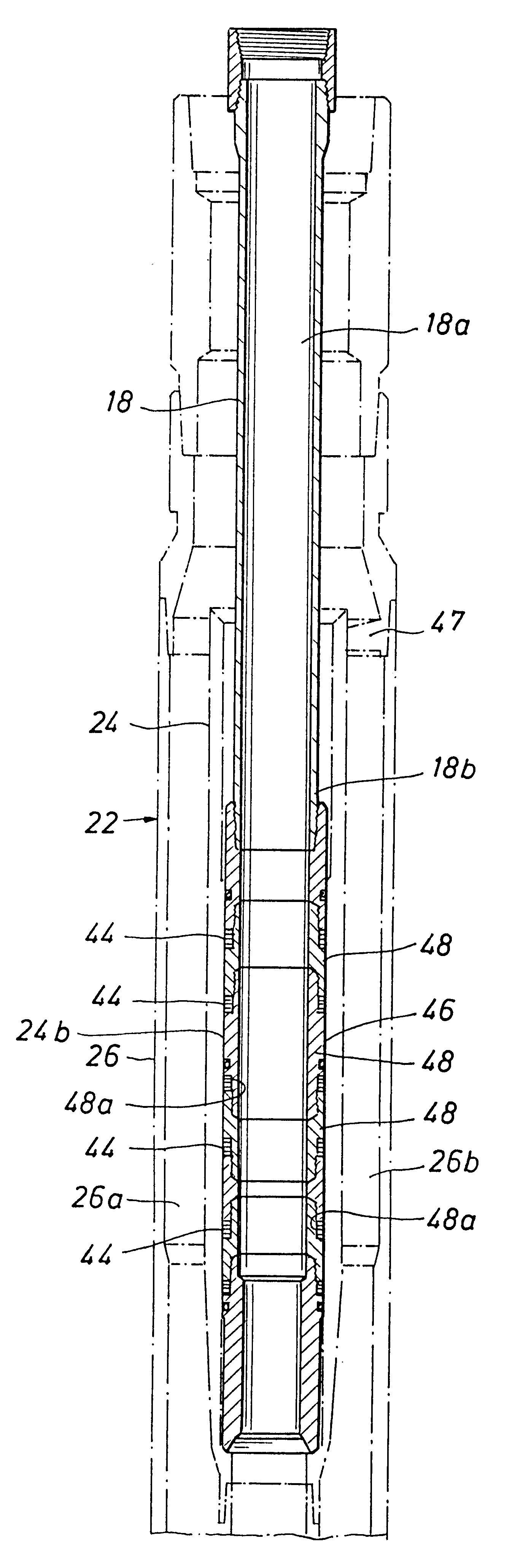
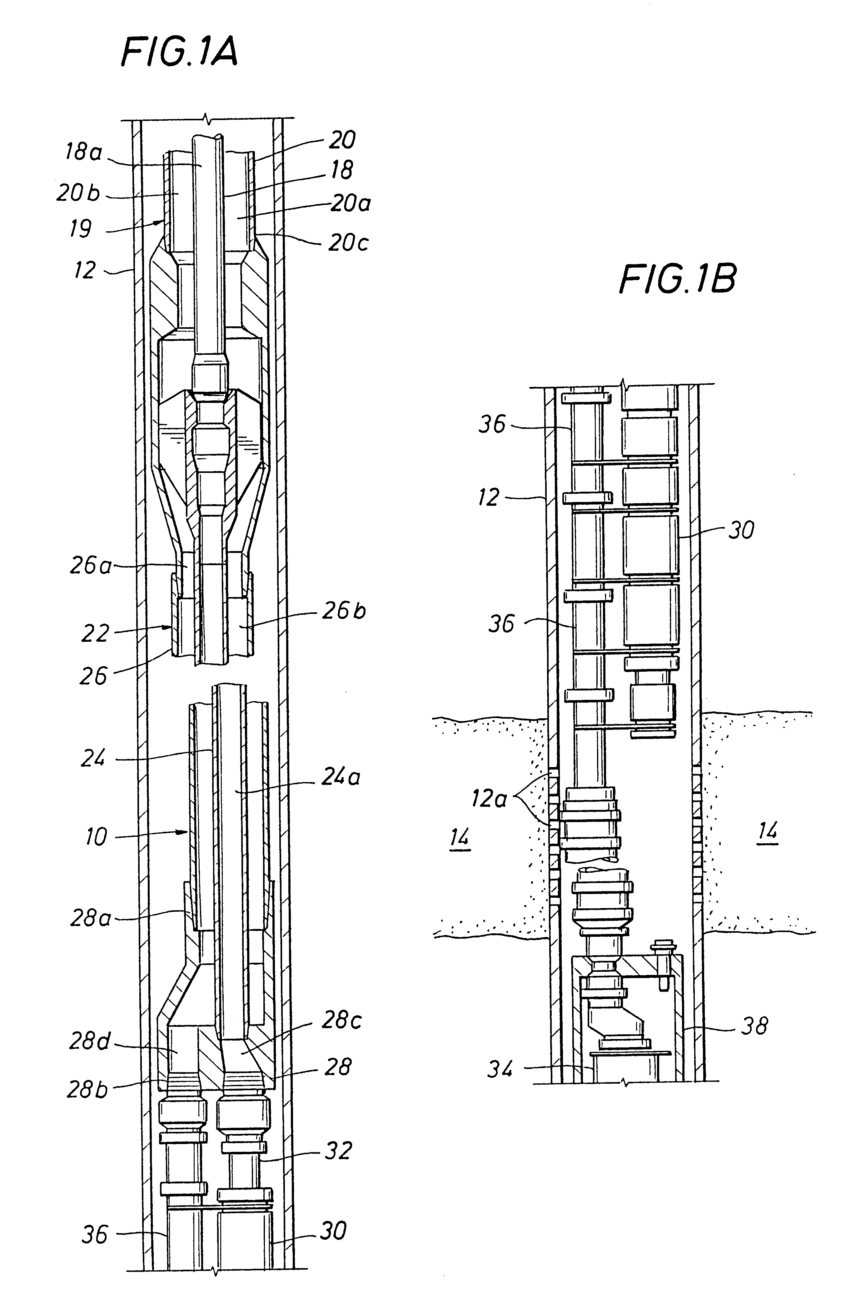
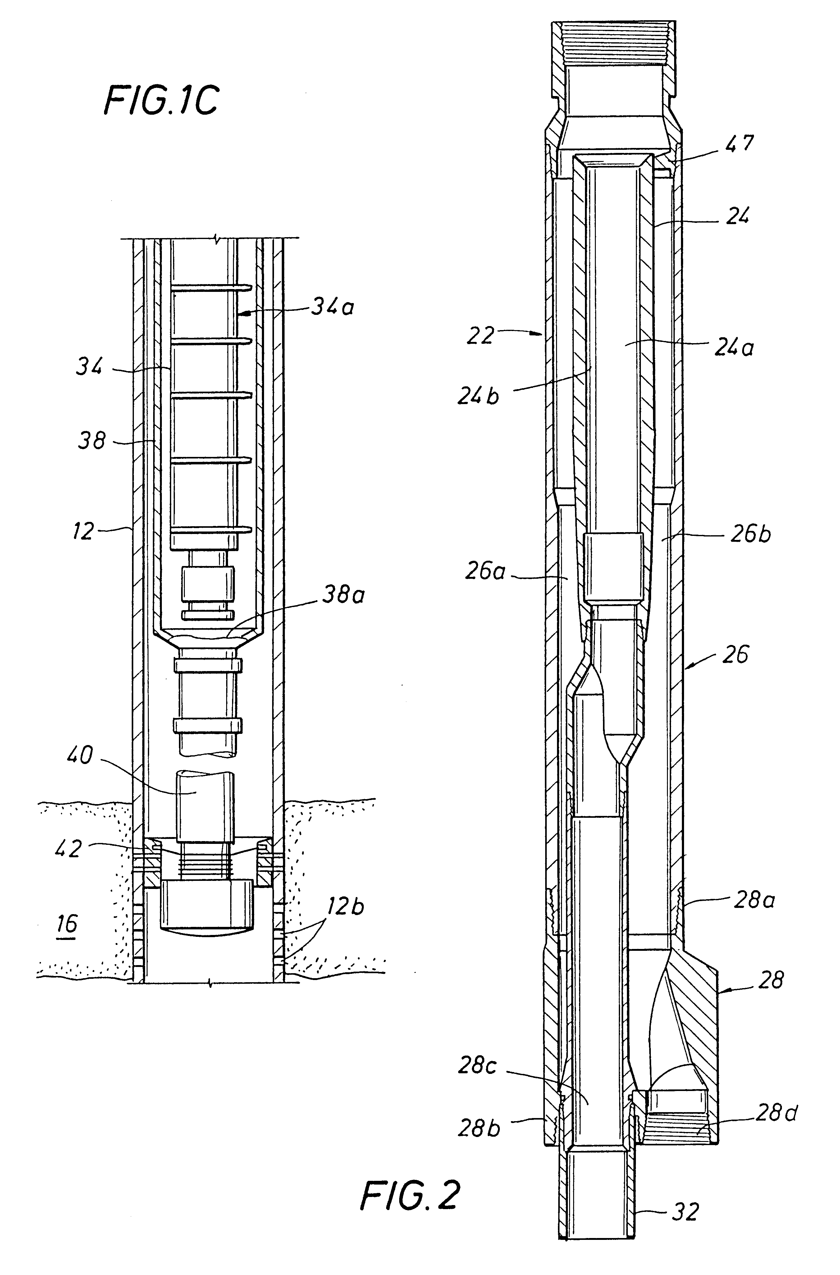
the artificial lift, concentric tubing production system of the present invention, generally designated as reference 10, is shown in FIGS. 1A, 1B, and 1C. The artificial lift, concentric tubing production system 10, hereinafter referred to as "first system," is installed in a well bore or casing 12. The first system 10 is for use in a well in which it is desired to separately produce production fluids from upper and lower formations 14 (FIG. 1B) and 16 (FIG. 1C), respectively. The casing 12 includes perforations 12a and 12b at the elevations of the upper and lower formations 14 and 16, respectively.
Referring to FIG. 1A, the first system 10 includes an inner production tubing string 18 and an outer production tubing string 20 extending down from a wellhead (not shown). The inner production tubing string 18 has an inner tubing bore 18a and the outer production tubing string has an outer tubing bore 20a. Preferably, the inner production tubing string 18 is concentrically located within...
second embodiment
the artificial lift, concentric tubing production system of the present invention, generally designated as reference 100, is shown in FIGS. 4A-4C. The artificial lift, concentric tubing production system 100, hereinafter referred to as "second system," is installed in a well bore or casing 112. The second system 100 is for use in a well in which it is desired to separately produce production fluids from a formation 114 (FIG. 4C). The second system 100 allows for the downhole separation and separate conduction of liquids and gases in the wellbore using a submersible transducer and separator. The casing 112 includes perforations 12a at the elevation of the formation 114.
Referring to FIG. 4A, the second system 100 includes an inner production tubing string 118 and an outer production tubing string 120 extending down from a wellhead (not shown). The inner production tubing string 118 has an inner tubing bore 118a and the outer production tubing string 120 has an outer tubing bore 120a. ...
third embodiment
the artificial lift, concentric tubing production system of the present invention, generally designated as reference 200, is shown in FIGS. 5A-5D. The artificial lift, concentric tubing production system 200, hereinafter referred to as "third system," is installed in a well bore or casing 212. The third system 200, like the second system 100, is for use in a well in which it is desired to separately produce production fluids from a formation 214 (FIG. 5D). The third system 200 allows for the downhole separation and separate conduction of liquids and gases in the wellbore using a submersible transducer and separator. The third system 200 is very similar to the second system 100. The casing 212 includes perforations 212a at the elevation of the formation 214.
Referring to FIG. 5A, the third system 200 includes an inner production tubing string 218 and an outer production tubing string 220 extending down from a wellhead W. The inner production tubing string 218 has an inner tubing bore ...
PUM
 Abstract
Description
Claims
Application Information