Motorized chair base

Inactive Publication Date: 2001-01-30
SUNNYBROOK & WOMENS COLLEGE HEALTH SCI CENT
View PDF10 Cites 94 Cited by
  • Summary
  • Abstract
  • Description
  • Claims
  • Application Information

AI Technical Summary

Benefits of technology

One advantage of the instant design is that it provides a stable low profile base for a chair, stretcher or the like. Accordingly, even though the base may be used in the construction of a midwheel drive chair, the base is stable not only when a user is entering or exiting the chair, but also while the chair is in operation over a variety of terrain. Further, the base maintains good stability and traction when travelling up or down a ramp. This is particularly important w

Problems solved by technology

Further, these chairs tend to lose traction on downward slopes since the rear drive wheels tend to become unloaded.
These complex manoeuvres are sometimes difficult for disabled persons to carry out.
However, these chairs also require a large turning radius and tend to lose traction when going uphill.
In addition, existing motorized wheelchairs frequently have difficulty in traversing uneven flooring or terrain or when travelling along an incline, such as a wheelchair ramp, and may lose traction
One disadvantage with this approach was that the free running wheels would rock forward to backward and/or side to side

Method used


Image

  • Motorized chair base
  • Motorized chair base
  • Motorized chair base

Examples


Embodiment Construction

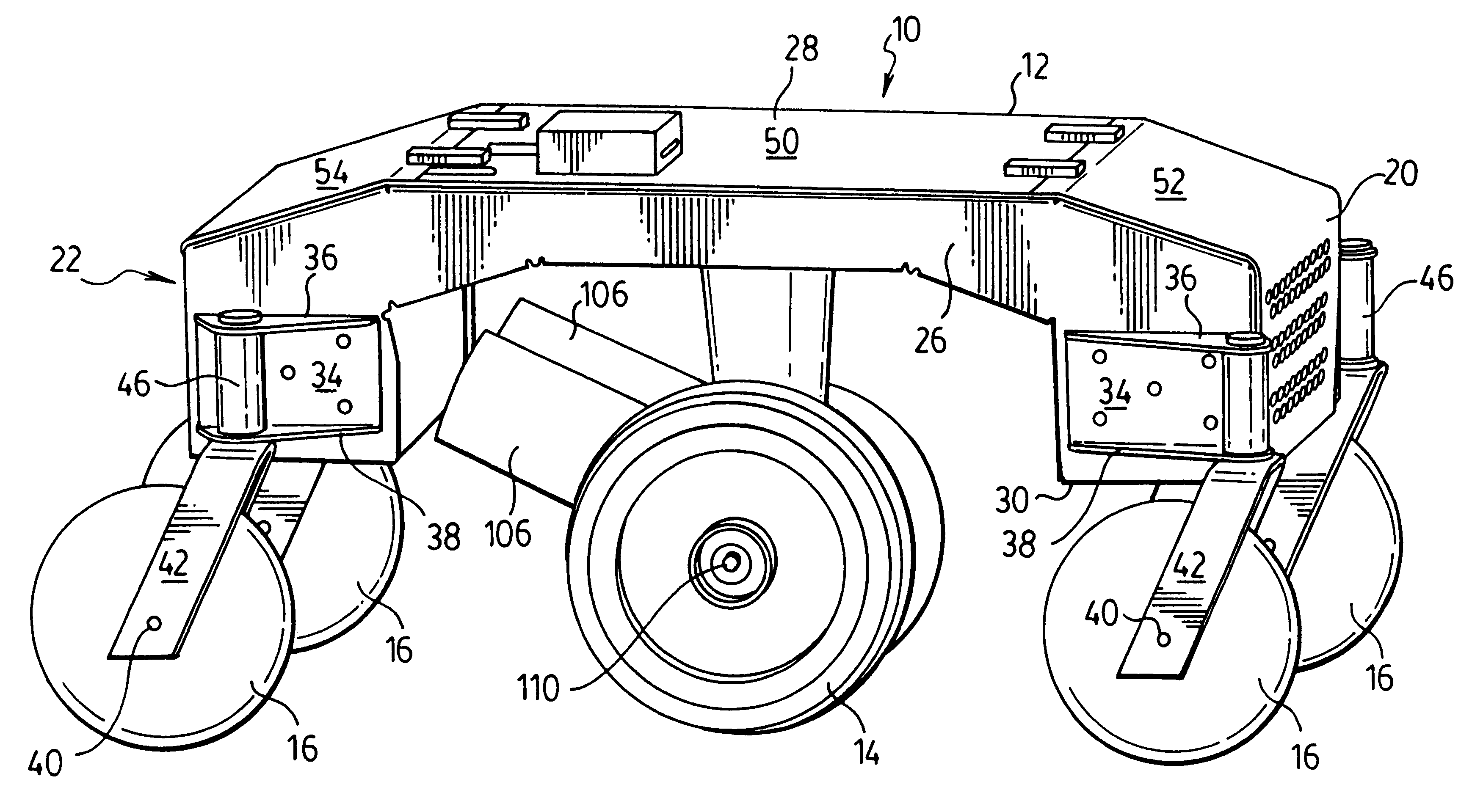
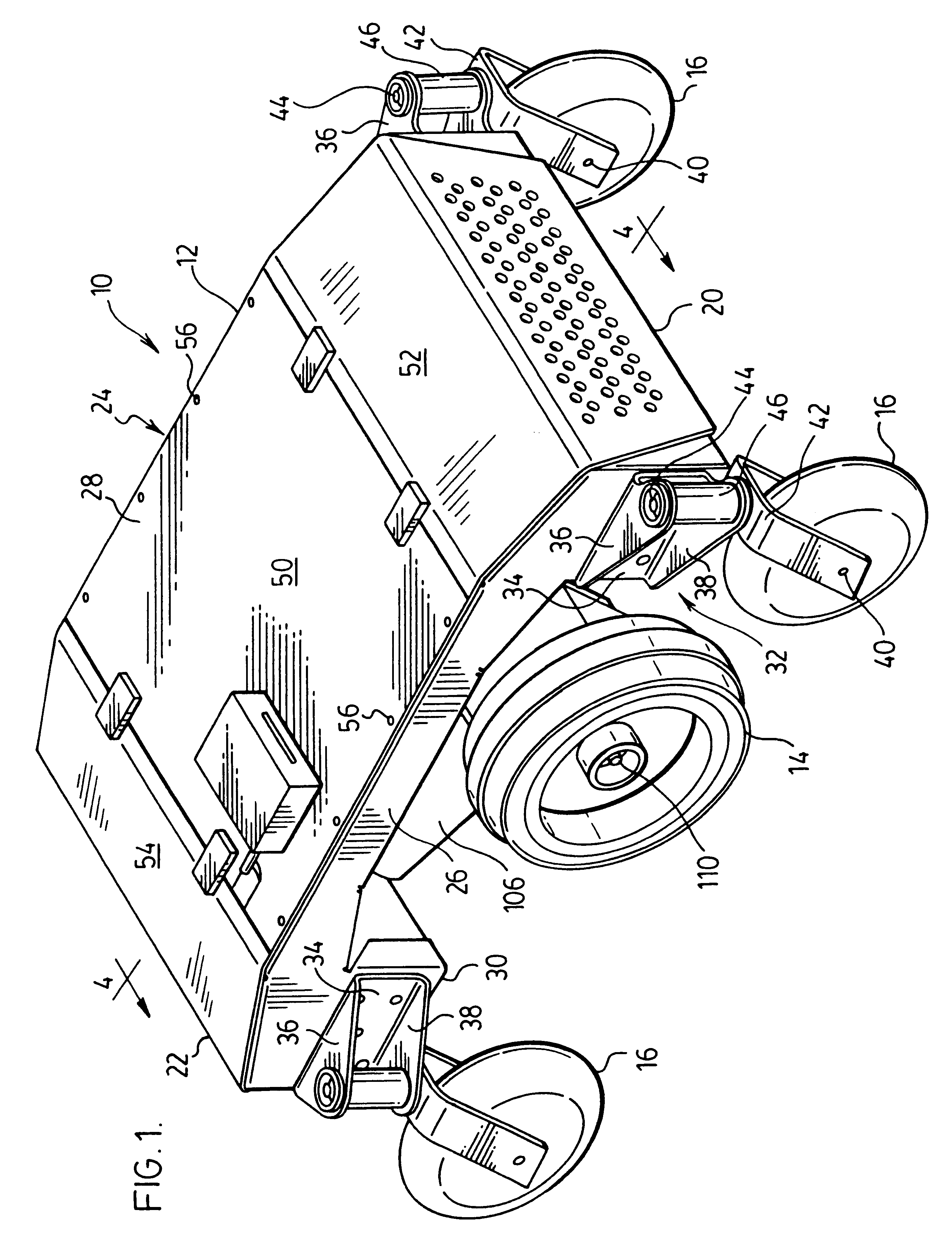
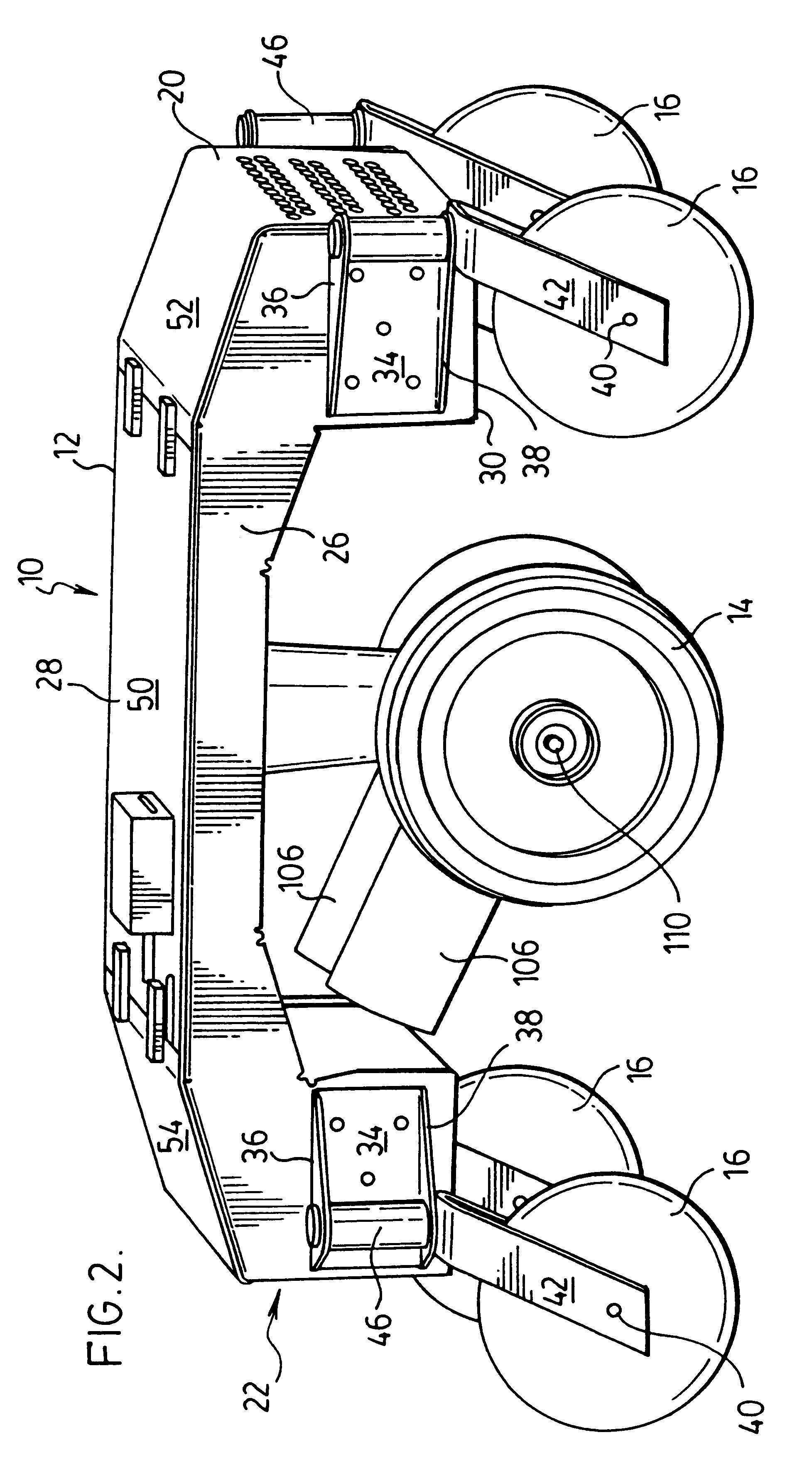
As shown in FIG. 1, motorized base chair 10 comprises a chassis 12, drive wheels 14 and free running wheels 16.

Chassis 12 has a front end 20, a rear end 22, a first opposed side 24 extending between front and rear ends 20 and 22, a second opposed side 26 extending between front and rear ends 20 and 22, a top 28 and a bottom 30 (see FIG. 4).

Base 10 may be used in the manufacture of a motorized transport device, such as a wheelchair or to support a stretcher or trolley to support a load. The following description is based on the use of base 10 for a wheelchair; however, it will be appreciated that base 10 may be modified to receive thereon the superstructure of a stretcher or other transportation device. Accordingly, a seat (not shown) may be affixed to top surface 28 by any means known in the art. Preferably, the seat which is affixed to the chair is a seat for a wheelchair so that, when assembled, the unit comprises a wheelchair. Motorized chair base 10 is particularly adapted for u...


PUM


Abstract

A base for receiving a seat has a longitudinally extending chassis having a front end, a rear end, a central portion positioned therebetween and opposed sides extending longitudinally between the front and rear ends; at least one drive wheel mounted below the central portion; a plurality of rotatably mounted wheels positioned around the chassis and mounted at a fixed distance below the chassis; and a biasing member associated with the at least one drive wheel to bias the at least one drive wheel to engage the surface on which the base is situated and reduce the weight supported by the rotatably mounted wheels whereby the rotatably mounted wheels support sufficient weight of the base and the unoccupied seat to define a stable platform.

Description

This invention relates to a motorized base for a transportation device, such as a wheelchair, a stretcher, or the like.Traditionally, powered wheelchairs have two drive wheels at the rear and two castor wheel, at the front. These chairs drive like a car in that they pivot about the rear of the chair. Accordingly, such motorized wheelchairs are generally adapted for movement either along a straight line or along a steered curved arc, somewhat in the same manner as an automobile. They require a significant turning radius and, as with a car, many manoeuvres must be executed backwards. Further, these chairs tend to lose traction on downward slopes since the rear drive wheels tend to become unloaded.If it is desired to realign the wheelchair, for movement from one fixed position in an entirely new direction, it is typically necessary to go through complex turning manoeuvres, somewhat similar to the three point turn utilized on occasion in operating an automobile. The manoeuvres require a...

Claims


Application Information

Patent Timeline
IPC IPC(8): A61G5/00A61G5/04
CPCA61G5/043Y10S180/907
Inventor FERNIE, GEOFFREY R.GRIGGS, GERALD T.
Owner SUNNYBROOK & WOMENS COLLEGE HEALTH SCI CENT
Why Eureka
Try Eureka