Turbojet pod with laminar flow

a technology of laminar flow and turbojet, which is applied in the direction of aircraft power plant components, lighter-than-air aircraft, transportation and packaging, etc., can solve the problems of unfavorable use, unfavorable aerodynamic air flow along the outer surface of the bay, and unfavorable us

Inactive Publication Date: 2001-01-30
SOC NATIONALE INDUSTRIELLE AEROSPATIALE SA
View PDF10 Cites 80 Cited by
  • Summary
  • Abstract
  • Description
  • Claims
  • Application Information

AI Technical Summary

Problems solved by technology

In this conventional architecture, the mobile elements constituted more particularly by the pivoting cowls positioned immediately behind the air intake box create significant discontinuities, which greatly disturb the aerodynamic air flow along the outer surface of the bay.
Thus, although this shape is optimized so that the theoretical air flow is laminar, at least around the front half of the bay, it is impossible to obtain such a flow in practice.
This leads to an undesired increase in drag compared with the theoretical value thereof.
Moreover, articulated cowls are thin and not very stiff structures.
Thus, in flight, they are subject to significant defo

Method used


Image

  • Turbojet pod with laminar flow
  • Turbojet pod with laminar flow
  • Turbojet pod with laminar flow

Examples


Embodiment Construction

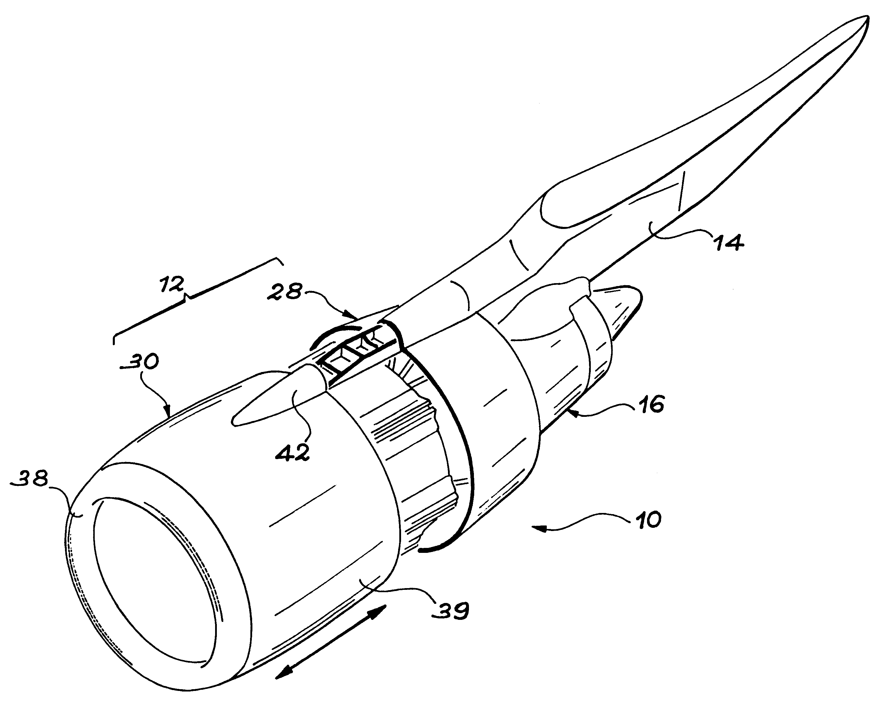
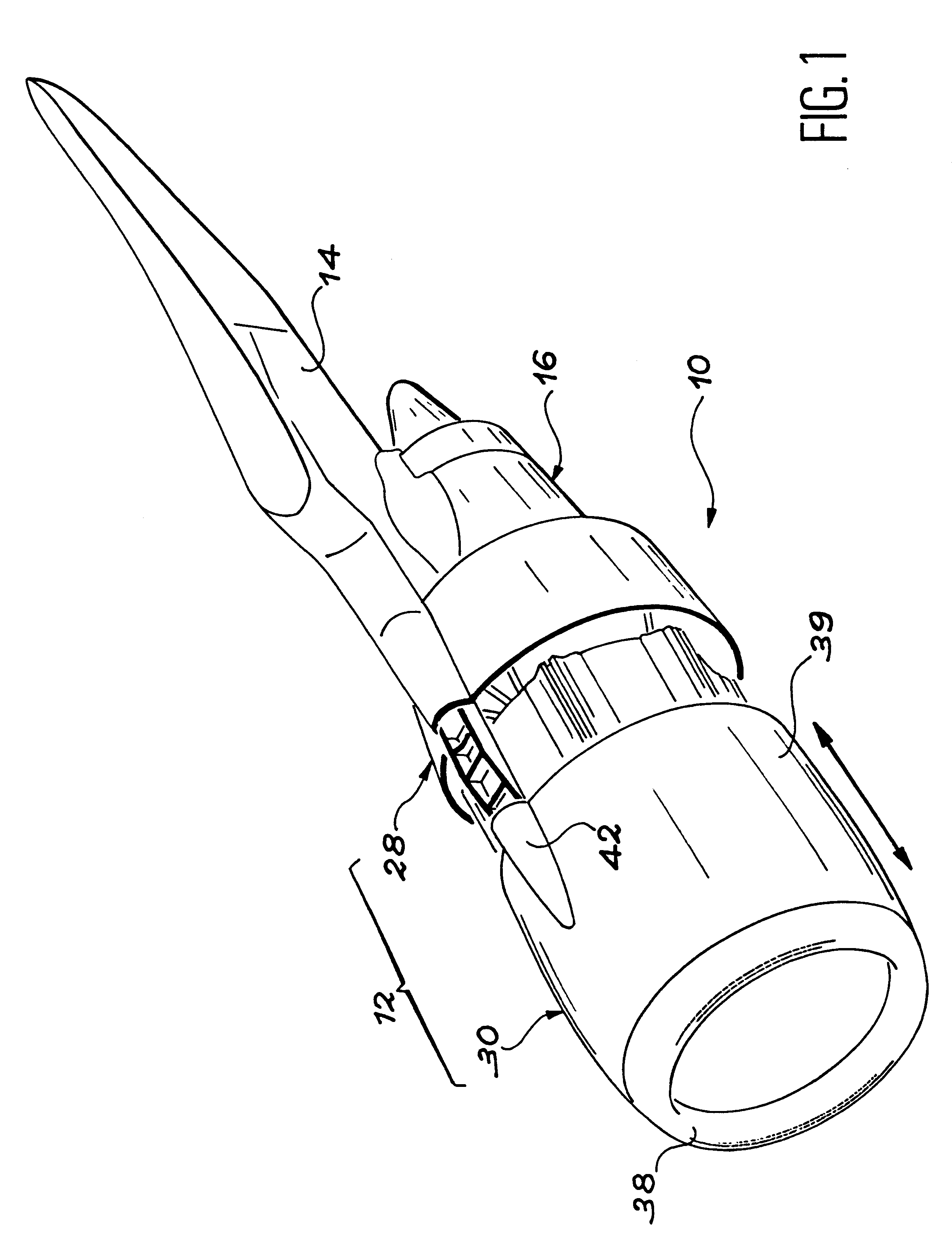
The invention relates to a jet engine bay, whose original architecture makes it possible to eliminate any discontinuity, at least over the front half of the external surface thereof, thus controlling both on the ground and in flight, the aerodynamic shape of said surface, so as to ensure there a laminar air flow, whilst rendering possible access to the region of the bay located around the jet engine fan.

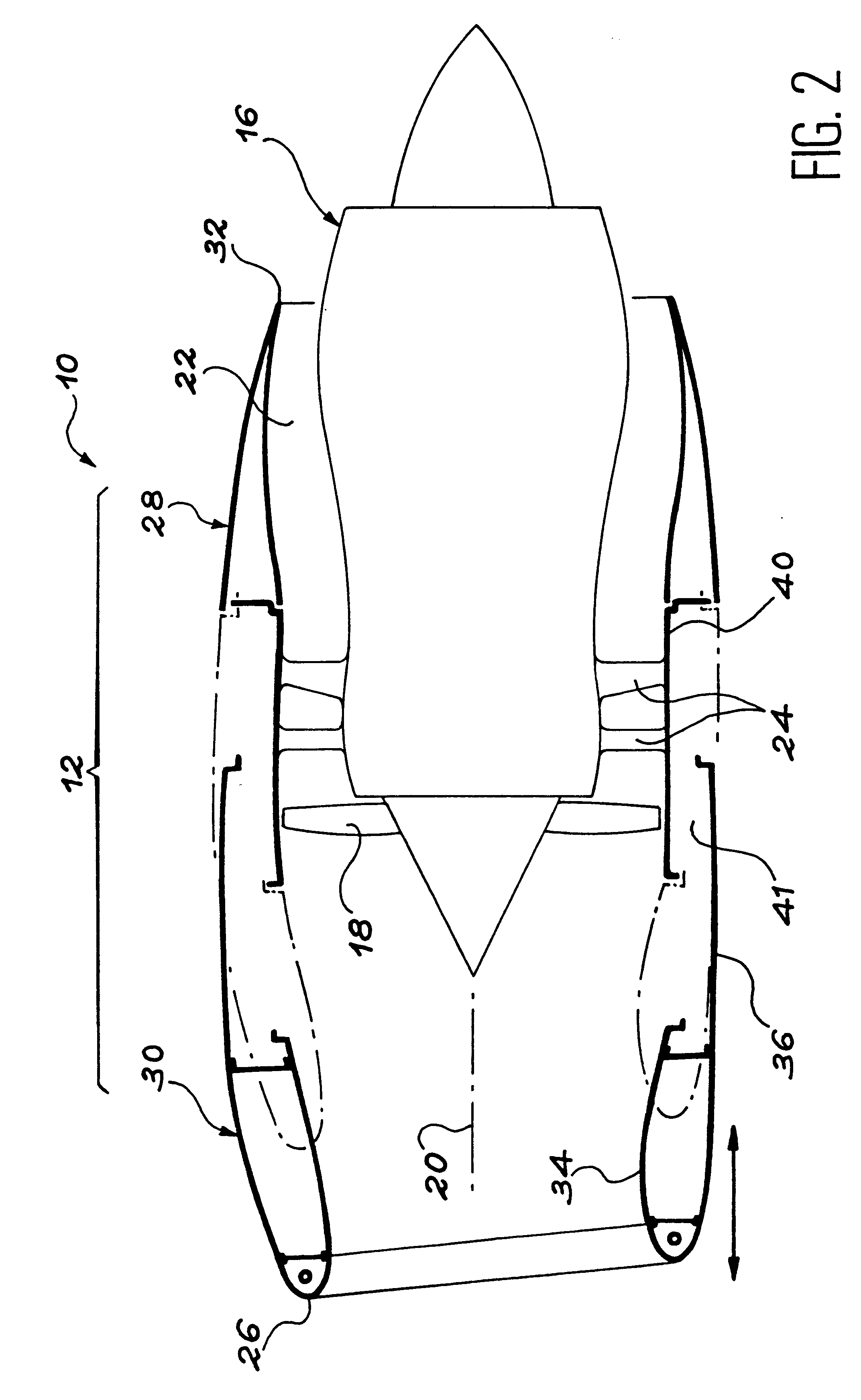
According to the invention, this result is obtained by means of a jet engine bay, characterized in that it comprises:

a rear structural element,

a front structural element, integrating an air intake box and an external shell extending rearwards and without any discontinuity, an external surface of the air intake box, so that the front structural element has a continuous, external surface extending over at least 50% of the geometrical chord of the bay,

maintenance and guidance means, interposed between the front structural element and a jet engine fan case, so as to allow a limited slidi...


PUM


Abstract

The bay (12) of a turbofan engine (10) comprises a front structural element (30), whose external surface is continuous and extends over at least 50% of the geometrical chord of the bay. Said element (30) is installed on maintaining and guiding members (44), such as slides, which prevent a significant deformation in flight and allow a sliding to the front of the element (30) for maintenance purposes. A laminar air flow around the front half of the bay (12) is consequently ensured.

Description

DESCRIPTION1. Technical FieldThe invention relates to a jet engine bay, whose architecture is optimized, so as to ensure a laminar air flow around the bay up to the vicinity of the thrust reversers. The invention more particularly applies to turbofan engine bay equipping aircraft.2. Prior ArtIn a turbofan engine, the bay channels around a core engine the secondary air flow produced by a fan, which is driven by a low pressure turbine forming part of the core engine.The mechanical connection between the jet engine and the aircraft wings is ensured by a structure known as a pylon. This complex structure ensures the transmission of forces and permits the passages of various circuits, particularly hydraulic circuits, linking the jet engine with the aircraft.Starting from the front of the engine in the air flow direction, the bay generally incorporates an air intake box, pivoting cowls giving access to an accessory box housed in the bay, thrust reversers and articulated cowls for the main...

Claims


Application Information

Patent Timeline
IPC IPC(8): B64D29/00B64D33/02B64D33/00
CPCB64D29/00B64D33/02B64D2033/0226
Inventor CANADAS, MARC
Owner SOC NATIONALE INDUSTRIELLE AEROSPATIALE SA
Why Eureka
Try Eureka