Information recording medium and method for producing the same

a technology of information recording medium and information recording medium, which is applied in the direction of magnetic materials for record carriers, light beam reproducing, instruments, etc., can solve the problems of destroying information pits preserved on adjacent tracks, unable to properly reproduce original information, and complicated recording means

Inactive Publication Date: 2001-01-30
CANON KK
View PDF16 Cites 37 Cited by
  • Summary
  • Abstract
  • Description
  • Claims
  • Application Information

AI Technical Summary

Problems solved by technology

If such a mark train is time-serially read out by the scanning of a light beam, the timing jitter of mark detection increases and so, there is the risk that the original information cannot be properly reproduced.
But, in this case, there is the problem that recording means becomes complicated.
Therefore, when recording or erasing is effected on the track by the application of a laser beam for heating, there arises the problem of cross write or cross erase that information pits preserved on adjacent tracks are destroyed by the heat diffusion to the adjacent tracks through the film surface.
Also, there has been the problem that the application of a sys...

Method used


Image

  • Information recording medium and method for producing the same
  • Information recording medium and method for producing the same
  • Information recording medium and method for producing the same

Examples


embodiment 1

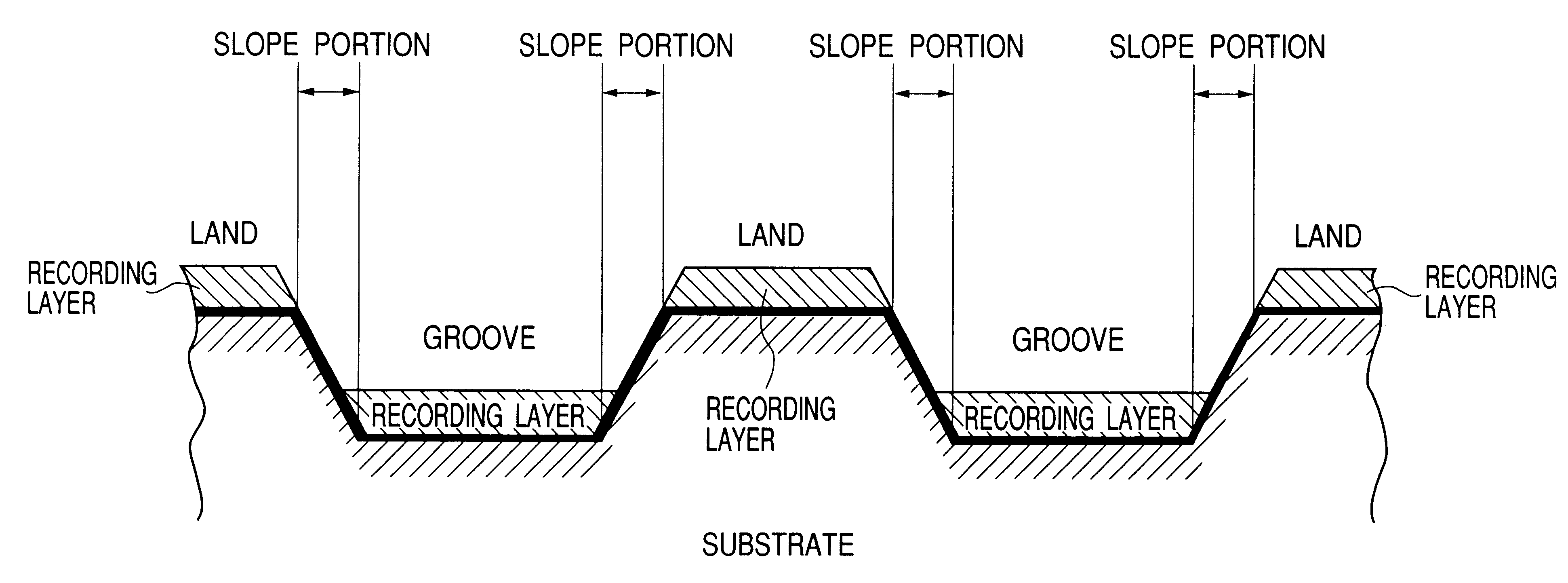
To improve productivity in the steps of Embodiment 1, it is better for the time required for etching to be as short as possible. A film forming step in which the recording layer is not laminated even if etching is not done is desirable.

For that purpose, it is preferable to adopt a film forming method which is as great as possible in the non-isotropy of the film forming speed and strong in directionality. For example, a film forming method such as the evaporation method which is capable of forming film basically in high vacuum is strong in directionality because particles emerged from the source keep travelling straight on. Also, even when the sputter method is used, low pressure sputter can be adopted or the applied voltage to the targets can be made high to thereby reduce the rate of going round and enhance directionality.

Further, it is also possible to use the collimate sputter method in which a grating-like collimate electrode is disposed in a film forming chamber in a direction ...

embodiment 2

Use was made of a substrate similar to that of Embodiment 1, with the exception that the pitch of the grooves was 1.1 .mu.m and the angle of inclination of the slope portions with respect to the surface of the substrate was about 76.degree.. The pressure of Ar gas during the formation of TbFeCo layer was 0.1 Pa, the supplied power to the targets was 1500 W, and the film was formed so that the film thickness might be 20 nm. Thereafter, a sample was made in the same manner as Embodiment 1, with the exception that without etching being effected, an SiN layer and an Al layer were formed.

In this sample, the angle of inclination of the slope portions of the substrate with respect to the surface of the substrate is great, the rate of going round during the formation of the TbFeCo layer is reduced, and the directionality is high and therefore, the recording film adheres only slightly to the slope portions even if etching is not effected.

When this sample was evaluated by a method similar to ...

embodiment 3

In Embodiment 2, the Al layer to be formed last was formed to a film thickness of about 100 nm. Thereafter, CCl.sub.4 was introduced as a reactive gas and the Al layer was etched by the plasma etching method until the film thickness thereof became about 50 nm. By this etching, the Al film on the slope portions was completely removed and the SiN layer formed immediately before it became exposed. Next, CF4 was introduced as a reactive gas, and this SiN layer was removed by the plasma etching method. As the result, a TbFeCo recording film slightly adhering to the slope portions became exposed. In the present embodiment, this recording film was not physically removed, but it was exposed to reactive gas for a predetermined time, whereby it was chemically changed in quality and the magnetism thereof was made to disappear so that it might not function as a recording film. When the sample thus made was evaluated by a method similar to that of Embodiment 1, an effect equal to that of Embodim...


PUM

PropertyMeasurementUnit
Angleaaaaaaaaaa
Angleaaaaaaaaaa
Temperatureaaaaaaaaaa

Abstract

In a method of producing an information recording medium, any recording film is not substantially formed on the slope portions of a substrate in which slope portions having surfaces non-parallel to the surface of the information track of an information recording medium are provided on the opposite sides of the information track. A recording film of a predetermined film thickness is formed on the information track.

Description

1. Field of the InventionThis invention relates to a method of producing an information recording medium, and an information recording medium produced by the method.2. Related Background ArtVarious optical recording media and magnetic recording media are known as information recording media comprising a substrate and recording film formed thereon. An optical recording medium for recording information thereon correspondingly to a change in an optical state detectable by light permits higher density and has been put into practical use as an optical disc or an optical card. Changes in an optical state formed on the optical recording medium include recess and projection bits, the presence or absence and deformation of reflecting film, changes in refractive index, reversal of magnetization, etc. Among these, reversal of magnetization is detected as a change in the polarized state of reflected light, and another form, it is detected as a change in the quantity of reflected light.Also, in ...

Claims


Application Information

Patent Timeline
IPC IPC(8): G11B11/00G11B11/105G11B7/26G11B7/24G11B7/007G11B5/74G11B7/24035G11B7/24073G11B7/24076G11B7/24085G11B11/10
CPCG11B5/74G11B7/24G11B7/26G11B11/10584G11B11/10586G11B11/10582G11B7/007Y10T428/24355Y10S428/90
Inventor SHIRATORI, TSUTOMUHONGU, KAZUOKI
Owner CANON KK
Why Eureka
Try Eureka