Annulus check valve with tubing plug back-up

Inactive Publication Date: 2001-02-13
ABB VETCOGRAY
View PDF11 Cites 46 Cited by
  • Summary
  • Abstract
  • Description
  • Claims
  • Application Information

AI Technical Summary

Benefits of technology

In one embodiment, the installation of the annulus plug is handled by retrieving the running tool. A retrieval tool is lowered into engagement with the tubing hanger. The retrieval

Problems solved by technology

It is expensive for a drilling rig to have a dual string completion riser in addition to a drilling riser.
Running on a drill string, however, does not readily allow a wireline plug to be installed in the annulus bore in the tubing hanger, because the drill string bore is aligned with the production bore.
Tubing hangers with various valves

Method used


Image

  • Annulus check valve with tubing plug back-up
  • Annulus check valve with tubing plug back-up
  • Annulus check valve with tubing plug back-up

Examples


Embodiment Construction

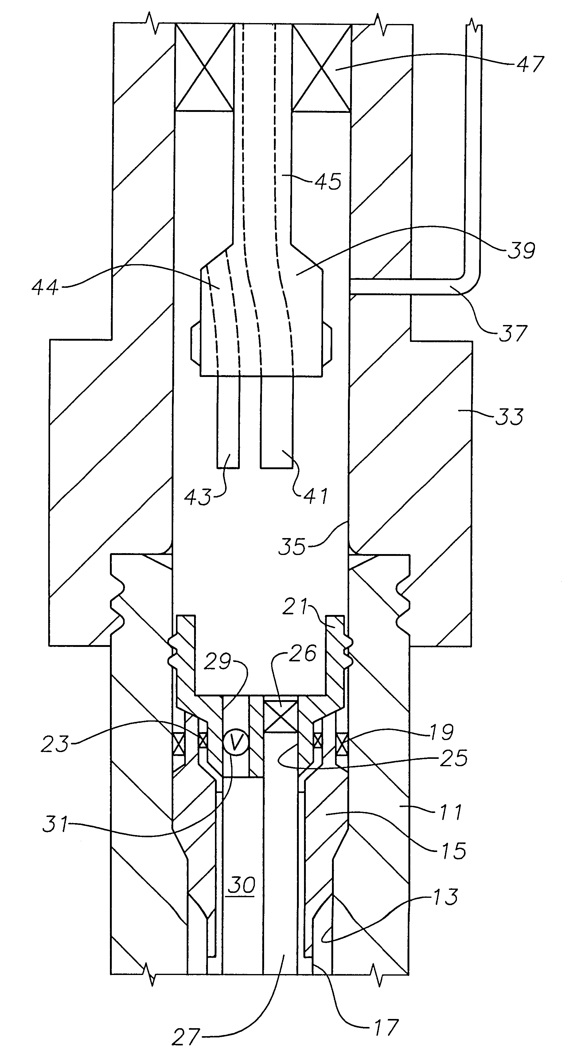
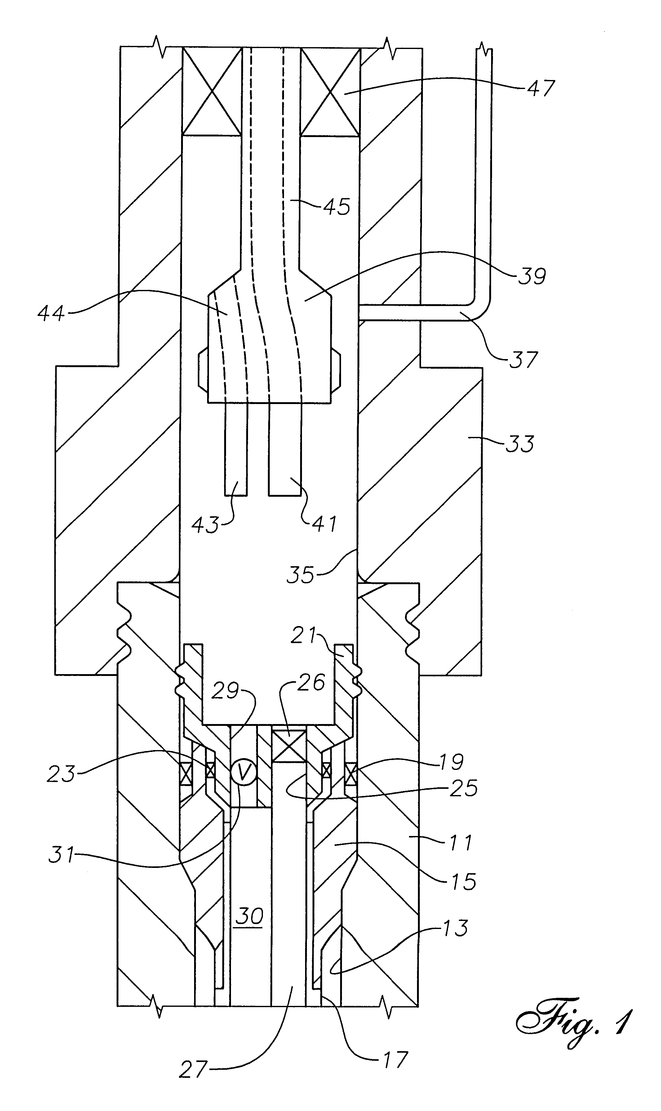
Referring to FIG. 1, a wellhead housing 11 is installed on the sea floor. Wellhead housing 11 has a bore 13. A casing hanger 15 is shown landed on a shoulder in bore 13. Casing hanger 15 is secured to the upper end of a string of casing. There will be additional casing hangers and casing strings which are not shown. Drill casing hanger seal 19 seals the casing hanger annulus between bore 13 and drill string 17.

A tubing hanger 21 is shown landed on casing string hanger 15. Tubing hanger 21 secures to the side wall of bore 13 and is supported on the upper end of casing hanger 15. A tubing hanger seal 23 seals the body of tubing hanger 21 to the bowl of casing hanger 15. Tubing hanger 21 has a production bore 25 extending through it and is secured to a string of tubing 27 extending into the casing string 17. A retrievable wireline plug 26 is shown installed in production bore 25. An annulus bore 29 is parallel to and offset from production bore 25 for providing communication from annul...


PUM


Abstract

A subsea well has a tubing hanger which has an annulus bore and a production bore. A check valve is located in the annulus bore. A running tool runs the tubing hanger on a monobore riser such as a drill string while holding the check valve in the open position. After setting and testing, the running tool is lifted and a blowout preventer is closed around the landing string. The operator monitors the choke and kill line of the drilling riser, which will be in communication with the check valve. If the check valve is leaking, an annulus plug may be installed in the annulus bore. The installation of the annulus plug may be handled by using a retrieval tool configured to align the annulus bore with the landing string passage. A wireline tool may be lowered through the landing string and retrieval tool to retrieve the check valve and install the plug. Alternately, the check valve may remain in the tubing hanger and the plug is set in the annulus bore above it. The check valve is retained in the open position, if so.

Description

This invention relates in general to subsea wellheads, and in particular to a tubing hanger having a production passage, an annulus passage, and a retrievable check valve in the annulus passage.A common method of completing a subsea well involves installing a high pressure wellhead housing at the sea floor. Multiple strings of casing will be supported at the wellhead housing and extend into the well. Then a tubing hanger with a string of tubing and other downhole equipment such as a packers, will be run into the casing and landed in the wellhead housing. The steps of drilling through the high pressure wellhead housing, running the casing and running the tubing are performed through a drilling riser and blowout preventer.The tubing hanger running tool will normally be attached to a dual completion riser which has one conduit in communication with a production bore in the tubing hanger and another conduit in communication with an annulus bore in the tubing hanger. The production and a...

Claims


Application Information

Patent Timeline
IPC IPC(8): E21B47/10E21B34/00E21B21/00E21B21/10E21B33/03E21B33/047E21B34/04
CPCE21B21/106E21B33/047E21B34/04E21B47/1025E21B47/117
Inventor VOSS, JR., ROBERT K.BRIDGES, CHARLES D.
Owner ABB VETCOGRAY
Why Eureka
Try Eureka