
Vehicle racking system

a racking system and vehicle technology, applied in the direction of vehicle transportation vehicles, vehicle carrying long loads, supplementary fittings, etc., can solve the problems of inability to use a tonneau cover, time-consuming and labor-intensive removal, and no effective use of the racking system for storage or carrying purposes

Inactive Publication Date: 2001-02-13
BURKE MALCOLM ROBERT
View PDF17 Cites 54 Cited by
  • Summary
  • Abstract
  • Description
  • Claims
  • Application Information

AI Technical Summary

Benefits of technology

It therefore is an object of the present invention to provide a racking system for a pick up vehicle

Problems solved by technology

The adoption of the abovementioned common feature provides a marked disadvantage in that it is not possible to utilise a tonneau cover for weather proofing purposes in regard to the pick up vehicle unless the mounting brackets or other mounting arrangements for the frame members or frame components of the prior art references are removed to facilitate attachment of the tonneau cover to each upper edge of opposed side walls of the pick up truck.
It can be appreciated that such removal is time consuming and may be labour intensive unless it is desired to dispense with use of a tonneau cover permanently by making the mounting brackets or other form of mounting arrangements in the form of permanent attachments to each side wall of the pick up truck.
Another disadvantage of these references is that no effective use could be made of the racking system for storage or carrying purposes when the. racking system was moved to an inoperative or folded position.
The base frame also incorporated a pair of end frames adjustably and releasably attached to a respective pair of end uprights, Manufacture of such a racking system was relatively expensive due to the relatively complicated structure of the racking system.
Installation and dismantling of the racking system in relation to individual pick up trucks was also time consuming and labour intensive.
Another disadvantage of this reference is that no effective use could be made of the racking system for storage or carrying purposes when the racking system was moved to a lowered or folded position.
However, while the frame structure of this reference is simple in nature, the racking system when moved to the inoperative position could not be effectively used for storage or storage of articles and especially when use was made of a tonneau cover for weatherproofing purposes.

Method used


Image

  • Vehicle racking system
  • Vehicle racking system
  • Vehicle racking system

Examples


Embodiment Construction

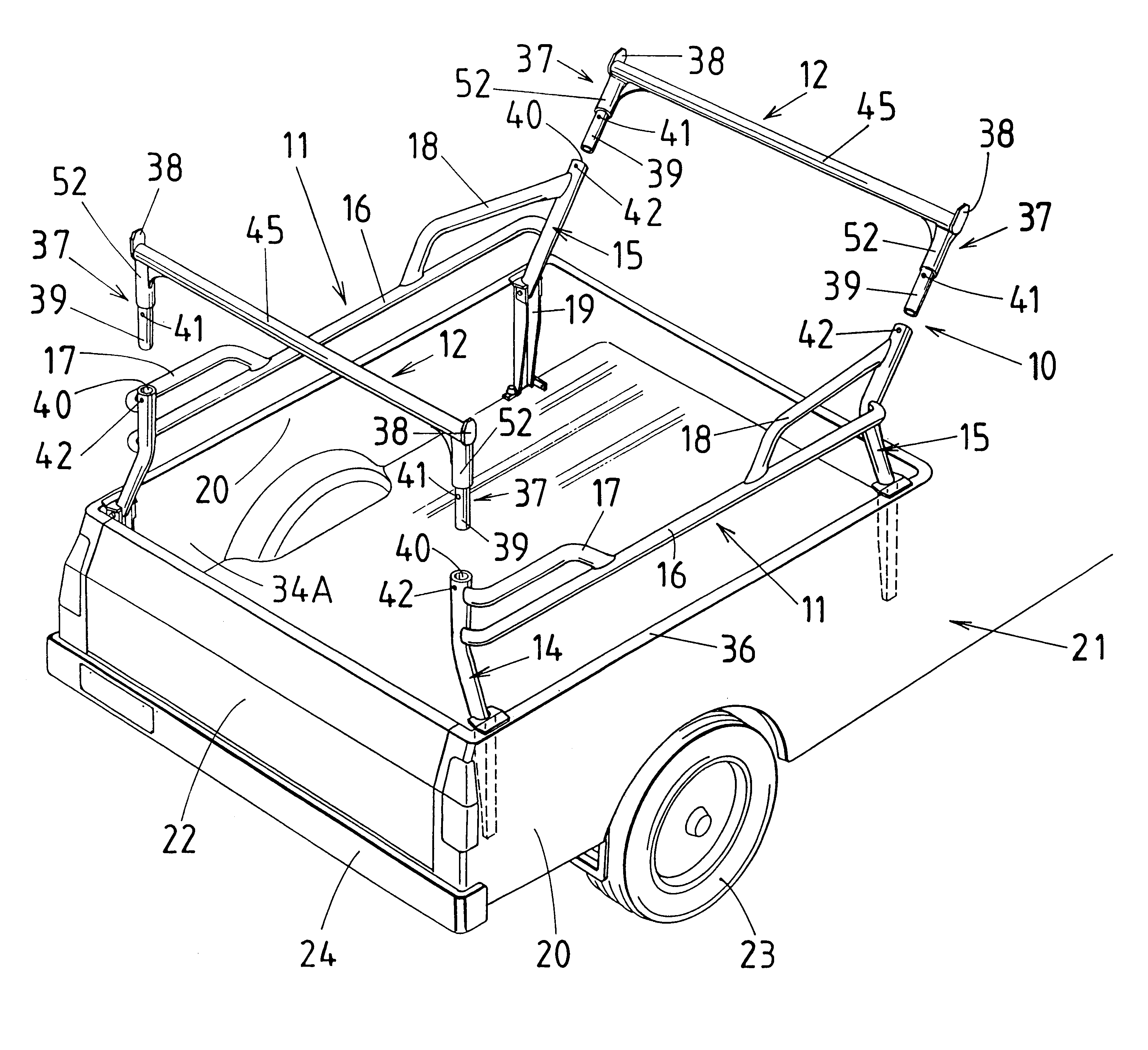
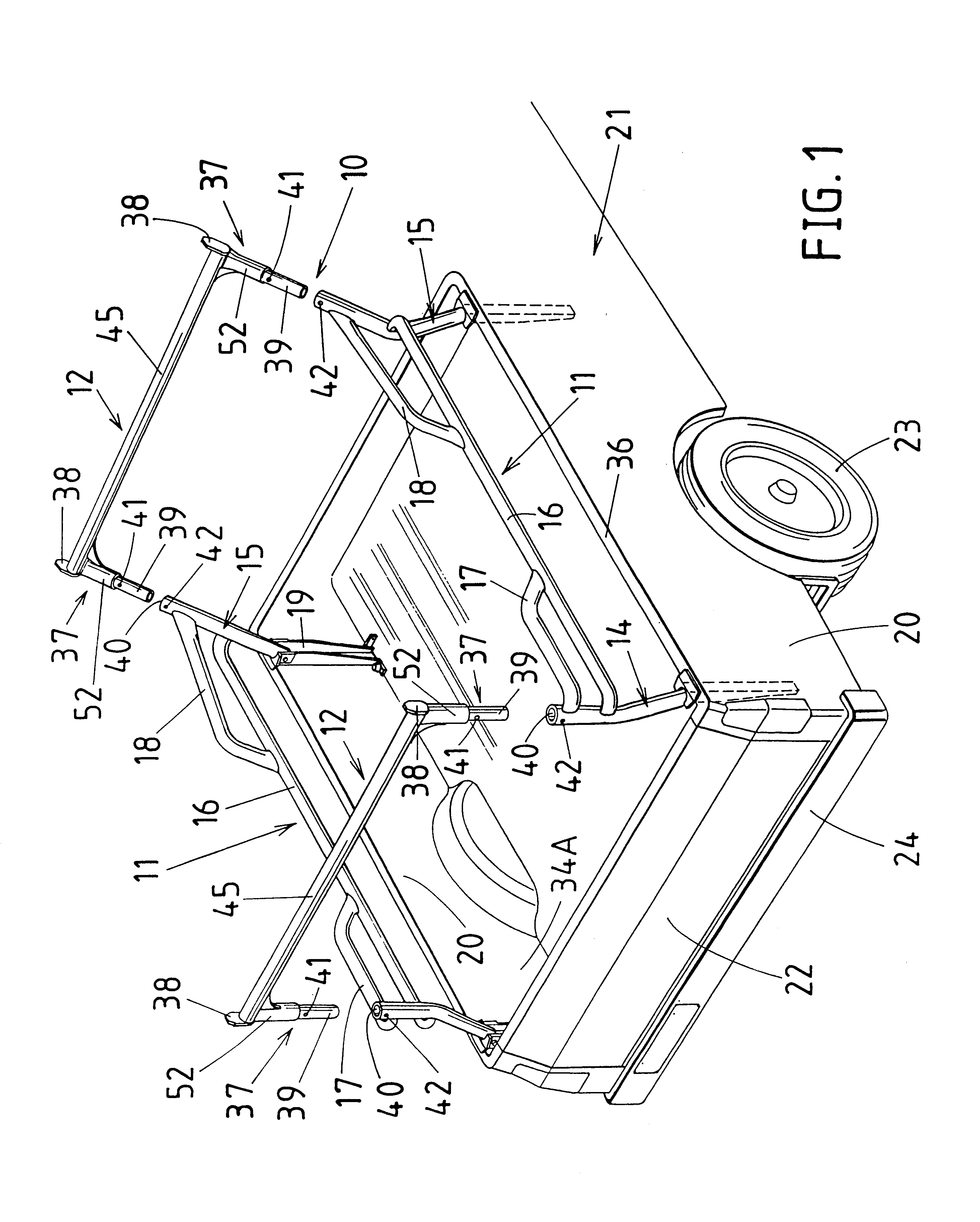
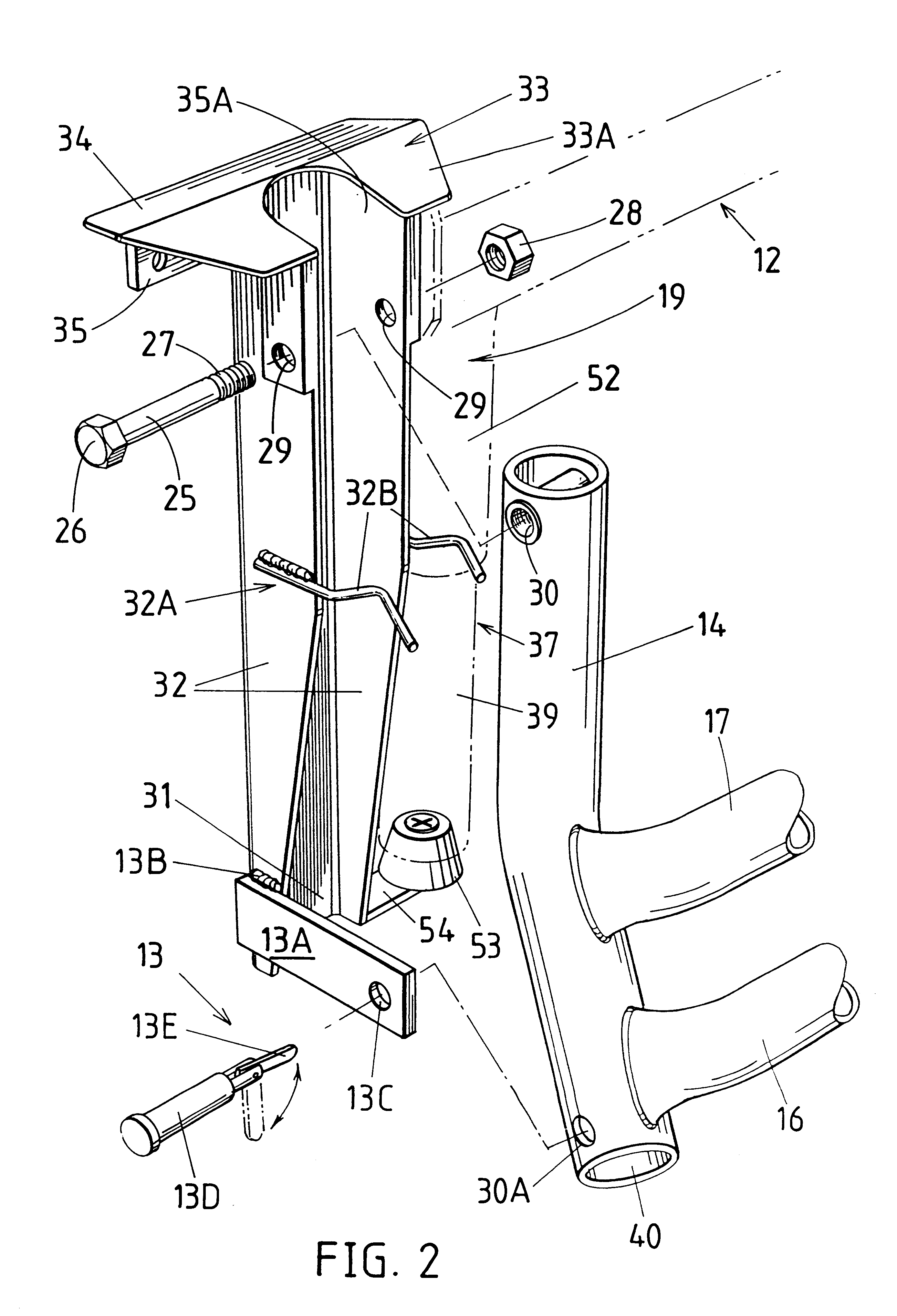
In the drawings, there is shown a racking system 10 comprising a pair of opposed side frames 11 and a pair of end frames 12. Each side frame 11 includes uprights 14 and 15 as well as tie bars 16, 17 and 18. Each upright 14 and 15 is pivotally attached to an associated pivot bracket 19 which is attached to an adjacent side wall 20 of vehicle 21. Vehicle 21 also Includes end wall 22, ground engaging wheels 23 and bumper bar 24. Each pivot bracket 19 has a pivot pin 25 having a head 26 and a screw-threaded portion 27 which is engageable with a nut 28. Pivot pin 25 is insertable through opposed apertures 29 of pivot bracket 19 as well as a tubular bush 30 of an associated upright 14 or 15 as best shown in FIG. 2. Pivot bracket 19 includes web 31, opposed flanges 32 and a top ledge component 33 having a flange 34 which engages with an adjoining top surface 36 of side wall 20 of vehicle 21. There is also provided a downwardly extending flange 35 which, when pivot bracket 19 is attached to...


PUM


Abstract

A racking system (10) for a pick up vehicle (21) including a pair of side frames (11) which are each mountable to an associated side wall (20) of the pick up vehicle (21) including one or more tie bars (16, 17, 18) and which side frames (11) are each pivotable about a longitudinal axis from an extended position to a lowered position and a pair of end frames (12) wherein each end frame (12) is releasably attachable to respective ends (37) of the pair of side frames (11) wherein the racking system (10) is self-bracing in the extended position.

Description

1. Technical FieldTHIS INVENTION relates to a racking system for vehicles and, in particular, utility vehicles or pick up vehicles inclusive of pick up trucks.2. BackgroundReference may be made to conventional racking systems for pick up trucks as described, for example, in U.S. Pat. No. 5,431,472. This reference describes a pair of end frames which are each attached to opposed support brackets located on an upper edge respectively of an associated side wall of a body of the pick up truck. There is also provided a retaining bracket on the upper edge of each side wall which is located intermediate a pair of the support brackets attached to a common side wall. The end frames may pivot from an upper operative position to a lower inoperative position whereby each end frame engages with an adjacent retaining bracket.Reference may also be made to conventional pick up truck racking systems which are described in U.S. Pat. Nos. 4,398,763, 4,604,013, 4,659,131, 5,002,324, 5,009,457, 5,037,15...

Claims


Application Information

Patent Timeline
IPC IPC(8): B60P3/40
CPCB60P3/40B60R9/00
Inventor BURKE, MALCOLM ROBERT
Owner BURKE MALCOLM ROBERT
Learn More