Apparatus and method for detecting motion vector

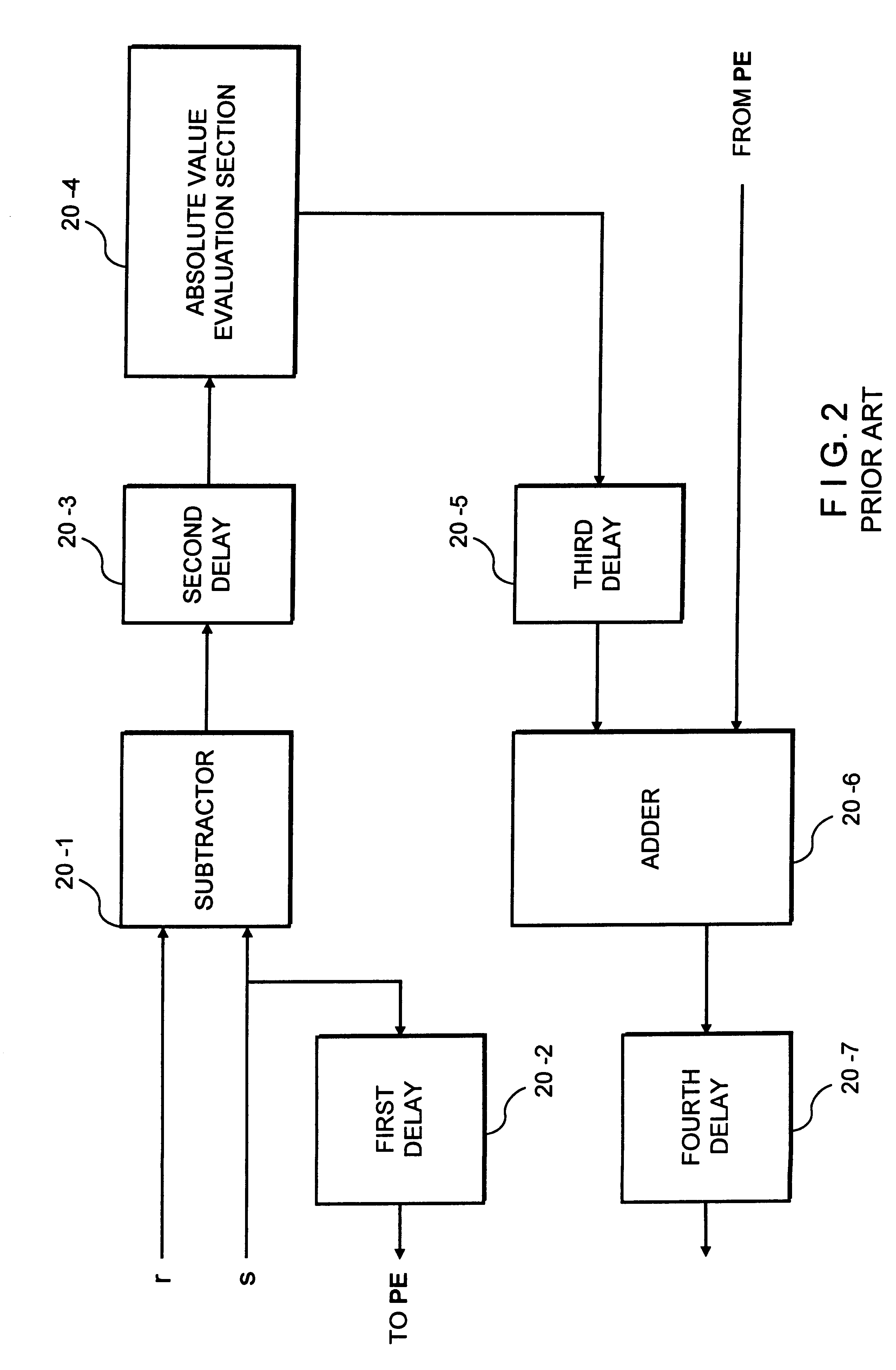
a technology of motion vector and detection apparatus, which is applied in the field of motion vector detection apparatus, can solve the problems of inability to use real-time picture compression, large amount of operations for the calculation of motion vector, and complicated configuration of each processing uni

Inactive Publication Date: 2001-02-13
HYUNDAI ELECTRONICS IND CO LTD
View PDF6 Cites 20 Cited by
  • Summary
  • Abstract
  • Description
  • Claims
  • Application Information

AI Technical Summary

Problems solved by technology

The calculation of the motion vector needs a large amount of operations.
With the high-speed digital processor, its algorithm is easy to change but its processing speed is limited, so that it cannot be used in real-time picture compression.
However, the configuration of each processing unit is so complicated, as shown in FIG. 2, that it is practically difficult to integrate a large number of processing units in a single chip.
However, the configuration of each processing unit (shown in FIG. 2) is so complicated that it is difficult for a large number of processing units to be integrated in a single chip.
However, this motion vector detection apparatus has also complicated configuration because of addition of processing unit such as the reliability judgement means, similar to the aforementioned conventional motion vector detection apparatus.

Method used


Image

  • Apparatus and method for detecting motion vector
  • Apparatus and method for detecting motion vector
  • Apparatus and method for detecting motion vector

Examples


Embodiment Construction

Reference will now be made in detail to the preferred embodiments of the present invention, examples of which are illustrated in the accompanying drawings. It should be noted in the drawings that like components are indicated by like reference numerals.

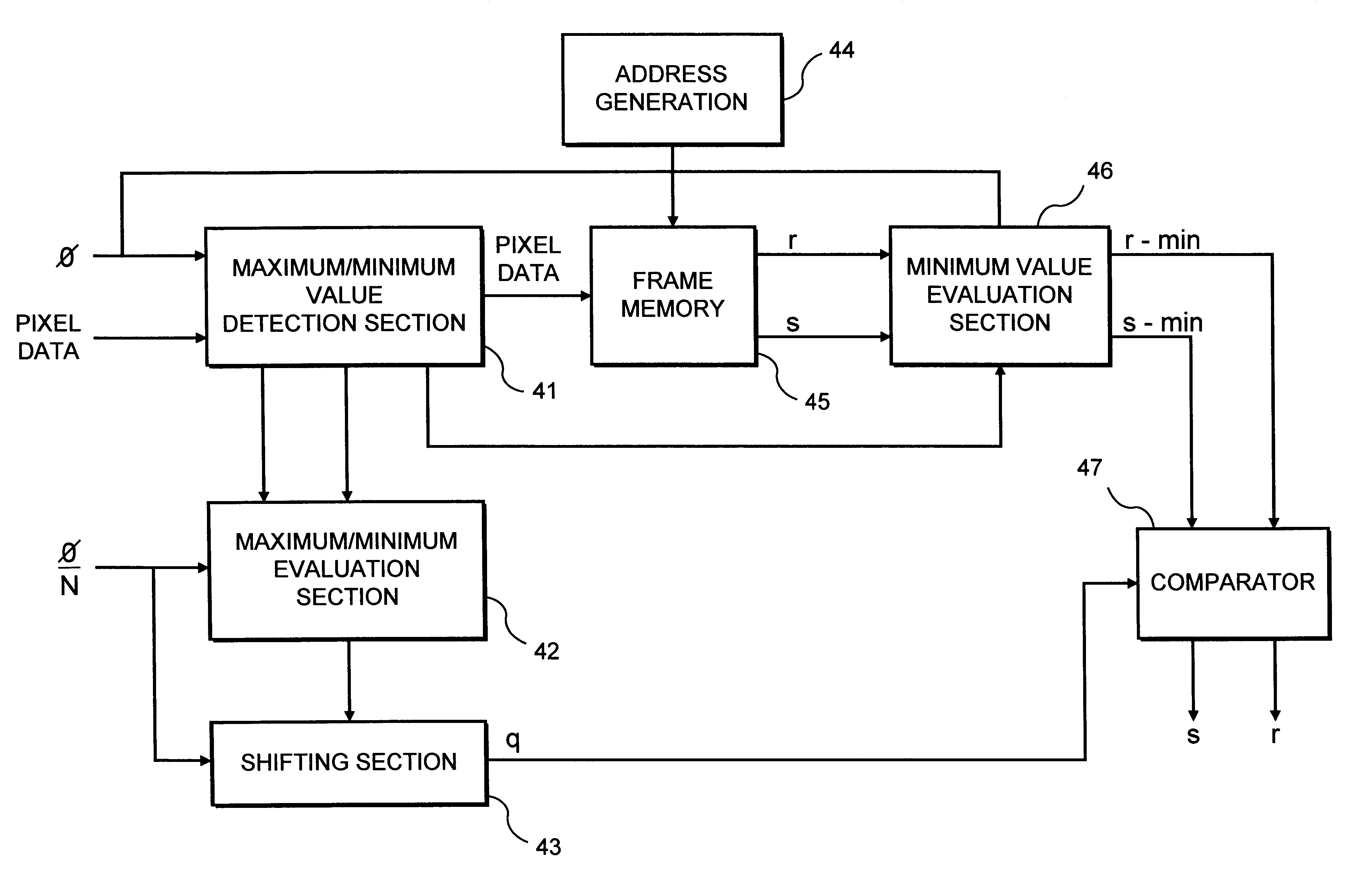
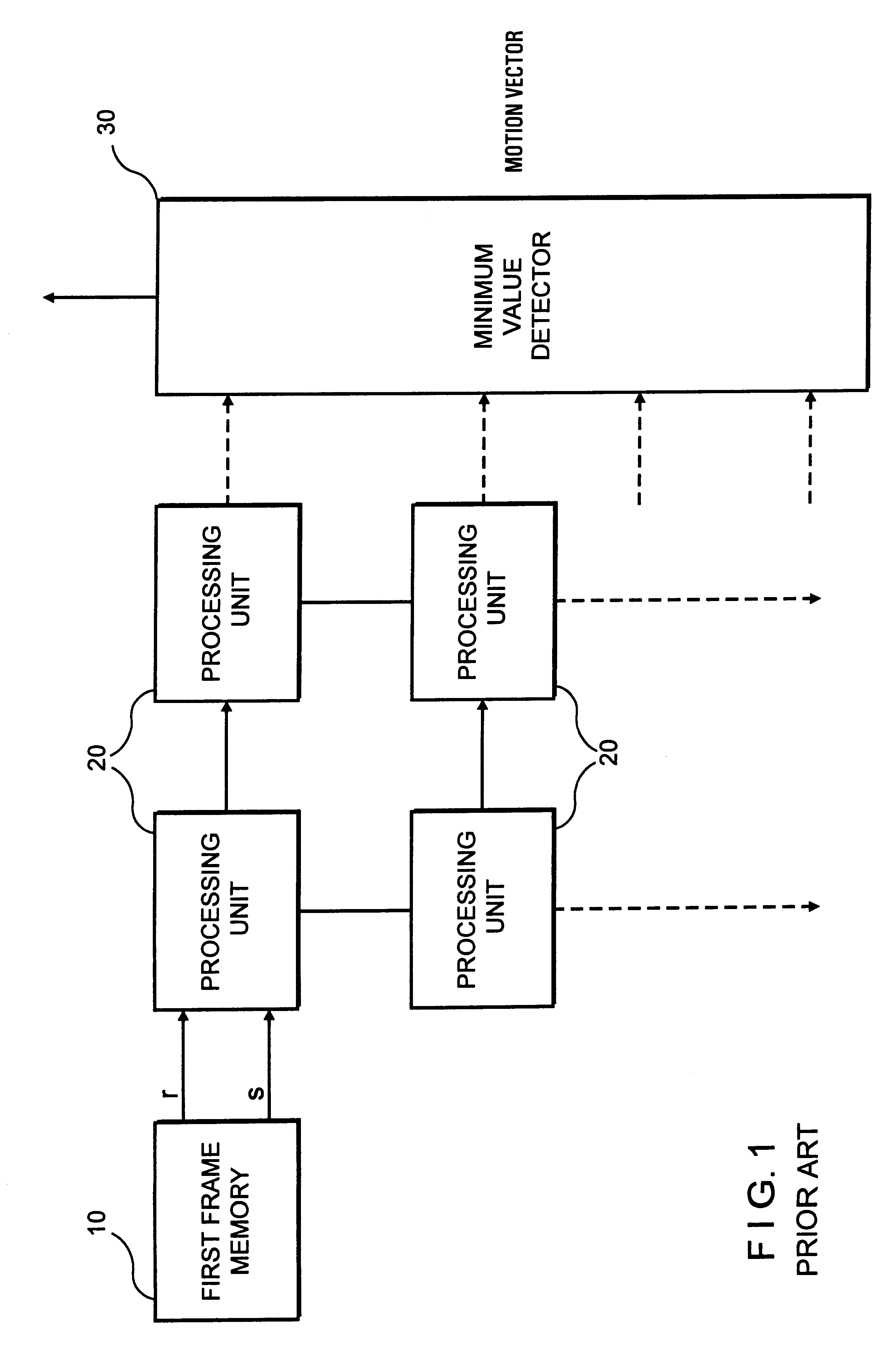
Referring to FIG. 3, the motion vector detection apparatus according to an embodiment of the invention includes: a quantizer 40 for inputting pixel data to receive value R of reference pixel and value S of pixel to be detected, and quantizing them; a plurality of processing units 20 connected to the output terminal of quantizer 40 in parallel, for receiving data outputted therefrom and calculating a motion vector; and a minimum value detector 30, connected to the output terminal of processing units 20, for receiving data outputted therefrom, and detecting its minimum value.

Referring to FIG. 4, quantizer 40 according to an embodiment of the invention includes: a maximum / minimum value detection section 41 for making the pixel data input...


PUM

PropertyMeasurementUnit
sizeaaaaaaaaaa
speedaaaaaaaaaa
processing speedaaaaaaaaaa

Abstract

A motion vector detection apparatus is disclosed, including: a quantizer for receiving a value of reference pixel and value of pixel to be detected, detecting their maximum values and minimum values, and determining a quantization level using the detected maximum values and minimum values, to quantize the value of reference pixel and value of pixel to be detected; a plurality of processing units for receiving data outputted from the quantizer, and calculating a motion vector, the processing units being connected to the output terminal of the quantizer in parallel; and a minimum value detector for receiving data outputted from the processing units and detecting its minimum value, the minimum value detector being connected to the output terminal of the processing units. The present invention constructs the processing units simply according to the quantization of data using the quantizer, to increase the integration of the processing units in a single chip, improving the processing speed.

Description

1. Field of the InventionThe present invention relates to a motion vector detection apparatus and, more particularly, to an apparatus for detecting motions between image frames continuously inputted, to calculate a motion vector in terms of pixel block.2. Discussion of Related ArtIn a computer vision field such as inspection and instrumentation, generally, motion vector calculation is required to detect where a reference model image is located in a frame to be detected. Security and supervision systems also need motion vector calculation to check if there is variation between image frames recorded at regular intervals. The computer vision field of inspection and instrumentation and security and supervision systems employ MPEG as a picture compression standard which uses a coding method according to motion correction between frames. This requires faster motion vector arithmetic.The detection of the motion vector requires the existence of a reference picture frame and frame to be dete...

Claims


Application Information

Patent Timeline
Patent Type & Authority Patents(United States)
IPC IPC(8): G06T7/20H04N7/26H04N7/50H04N5/14H01F38/42H04N3/19H04N19/50H04N19/126H04N19/136H04N19/176H04N19/196H04N19/42H04N19/51H04N19/57
CPCG06T7/2013H04N5/145H04N19/51H04N19/61H04N19/126H04N19/98G06T2207/10016G06T7/223H01F38/42H04N3/19
Inventor LEE, YOUNG
Owner HYUNDAI ELECTRONICS IND CO LTD
Why Eureka
Try Eureka