
Double bearing reel

a double bearing, reel technology, applied in the direction of reels, applications, fishing, etc., can solve the problem that the mechanism 44 requires a certain amount of time to engage/disengag

Inactive Publication Date: 2001-02-20
SHIMANO INC
View PDF12 Cites 43 Cited by
  • Summary
  • Abstract
  • Description
  • Claims
  • Application Information

AI Technical Summary

Benefits of technology

Herein, since the first braking mechanism and the sounding mechanism may be switched at the same time using the switching operation mechanism, reel switching operations necessary for fishing are simplified, as compared with reels in which the first braking mechanism and the sounding mechanism are operated separately.
A double bearing reel in a still further aspect is the foregoing double bearing reel, further including a second braking mechanism which applies a braking force to the spool to prevent the spool from rotating in the line releasing direction when the clutch mechanism is in the coupled state. Herein, by setting the braking force applied by the second braking mechanism weaker than that of the first braking force, the live bait may freely swim in the water while applying the weaker force to the spool using the second braking mechanism. Then, when a fish is caught, the clutch mechanism may be turned so that a larger braking force is applied to the spool by the second braking mechanism to help land the fish. Accordingly, using the two braking mechanisms having the different levels of braking force enables drifting live bait and landing fish without switching the braking force.
A double bearing reel in a further aspect is the foregoing double bearing reel, wherein the braking adjustment mechanism includes an adjustment member rotatably fitted to the reel body, and a cam mechanism for contacting the pressing member. The cam mechanism rotates cooperatively with, and reciprocates along the rotational axis of, the adjustment member. The pressing member is disposed between the cam mechanism and the first rotation member. The reciprocating movement of the cam mechanism varies compressing force applied to the first rotation member by the pressing member. Herein, since the braking force is adjusted by the cam mechanism pressing on the pressing member in the rotational axis direction, the pressing force is restricted in comparison with a configuration in which the pressing member is compressed by screws. The braking adjustment mechanism is therefore less subject to damage.
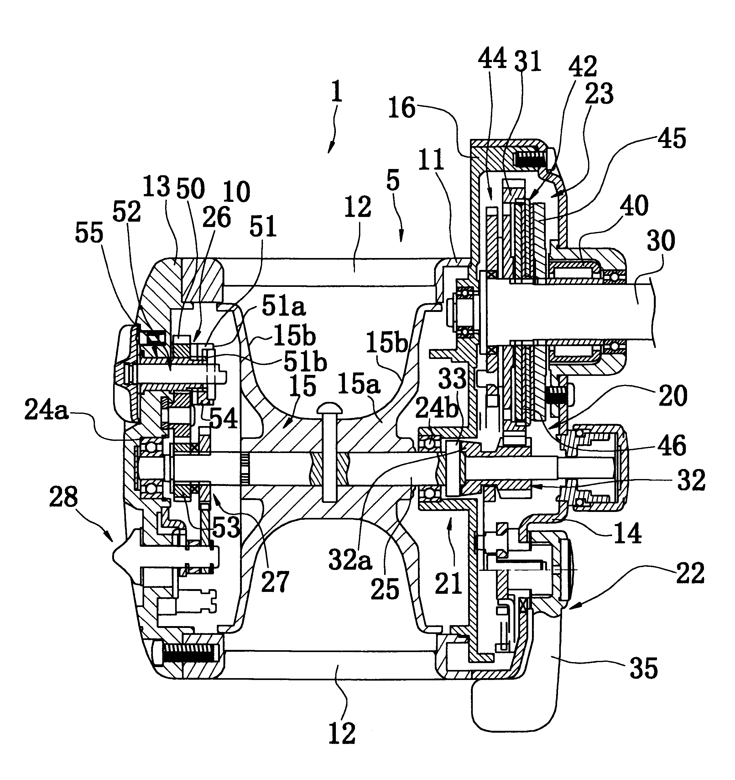
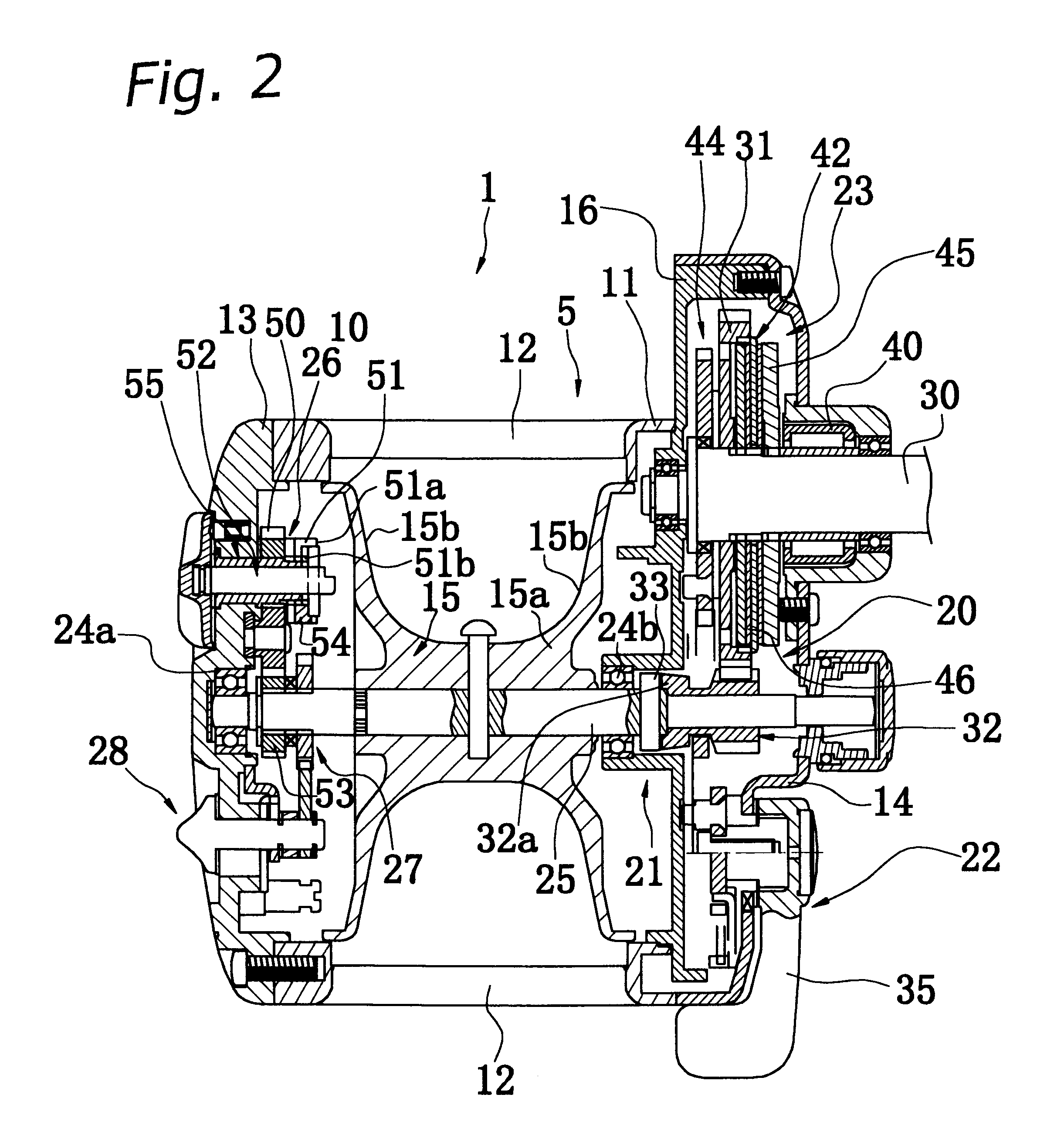
A double bearing reel in a still further aspect is the foregoing double bearing reel, wherein the sounding mechanism includes a disk-shaped jagged member having circumferentially spaced outer peripheral projections formed side by side. The jagged member rotates cooperatively with the spool. The sounding mechanism also includes a sounding member, disposed such that one is movable into a sounding position between the peripheral projections of the jagged member and into a separated position wherein the end is parted away from the peripheral projections. In the sounding position, rotation of the jagged member vibrates the sounding member. The switching operation mechanism moves the sounding member between the sounding position and the separated position. Herein, when the sounding member is put into the sounding position by the switching operation mechanism, the first braking mechanism is switched to the braking state. When the spool rotates in this state, the end of the sounding member vibrates by repeatedly colliding with the peripheral projections on the jagged member rotating cooperatively with the spool, producing a clicking sound. At the same time, the spool is braked. Further, when put into the separated position, the first braking mechanism is switched to the non-braking state and no sound is produced when the spool rotates, reducing rotational resistance on the spool. The sounding state and sound-disabled state are effected by the sounding member contacting / parting on / off the peripheral projections on the jagged member. Thus a simple mechanism reliably realizes the two states.
A double bearing reel in still another aspect is the foregoing double bearing reel, wherein the sounding member is moveable radially with respect to the jagged member, and the handling member is provided on the reel body to be movable in the said radial direction. The handling member moves the sounding member from the sounding position to the separated position, the latter being shifted in the said radial direction from the former. Herein, making the sounding member movable using the handling member in the radial direction with respect to the jagged member simplifies the structure of the handling member.
The double bearing reel in one further aspect of the present invention is the foregoing double bearing reel, further including a regulating means for regulating rotational position of the converter member in the coupled position. Herein, regulating the coupling member from over-travel in the coupled position keeps rotational resistance generated when the fishing line is released from being large. Further, the rotational resistance not being large is thus not heavy on the operation of moving the handling member in shifting it into the parted away position.

Problems solved by technology

The two operations therefore have to be carried out to respond to the fishing conditions, and particularly when a fish is caught and fishing line reeled in while landing the fish, performing the two complex operations is an involved task.
However, the ratchet mechanism 44 requires a certain amount of time to engage / disengage the ratchet pawl with / from a ratchet wheel.

Method used


Image

  • Double bearing reel
  • Double bearing reel
  • Double bearing reel

Examples


Embodiment Construction

(a) Although the spool 15 is indirectly braked by braking the first gear 50 connected with the spool 15 in the frictional braking mechanism 26 in the above-mentioned embodiment, the configuration of he frictional braking mechanism 26 is not limited as such. For instance, it is possible to directly brake the spool 15 or the spool shaft 25. In such a case, the position of the pressing member pressing the spool 15 or the spool shaft 25 may be switched between a position where it presses the spool 15 or the spool shaft 25 and a position where it is placed away from the spool 15 or the spool shaft 25. Also, the first braking mechanism is not limited to the one utilizing friction in order to achieve braking and braking mechanisms utilizing induced electromagnetic force or viscosity of a fluid may be used.

(b) Although the sounding mechanism 27 produces sound when it makes contact with the convex portions provided with the spool shaft 25 in the above-mentioned embodiment, the configuration ...


PUM


Abstract

A double bearing reel that facilitates operating the braking and sounding mechanisms while fishing. A reel includes a reel body having a handle (2), a spool (15), a clutch mechanism (21), a frictional braking mechanism (26), a sounding mechanism (27), a switching operation mechanism (28), and a drag mechanism (42). The frictional braking mechanism is capable of braking the spool in its braking state regardless of the state of the clutch mechanism and switchable between the braking state and a non-braking state. The sounding mechanism is capable of producing sound in accordance with the rotation of the spool and switchable between an engaged state in which sound may be produced and a disengaged state in which no sound is produced. The switching operation mechanism is capable of switching, at the same time, the states of both the sounding mechanism and the first braking mechanism from the engaged state and the braking state, respectively, to the disengaged state and the non-braking state, respectively, or vice versa. The drag mechanism brakes the rotation of the spool in the line releasing direction while the clutch mechanism is turned on.

Description

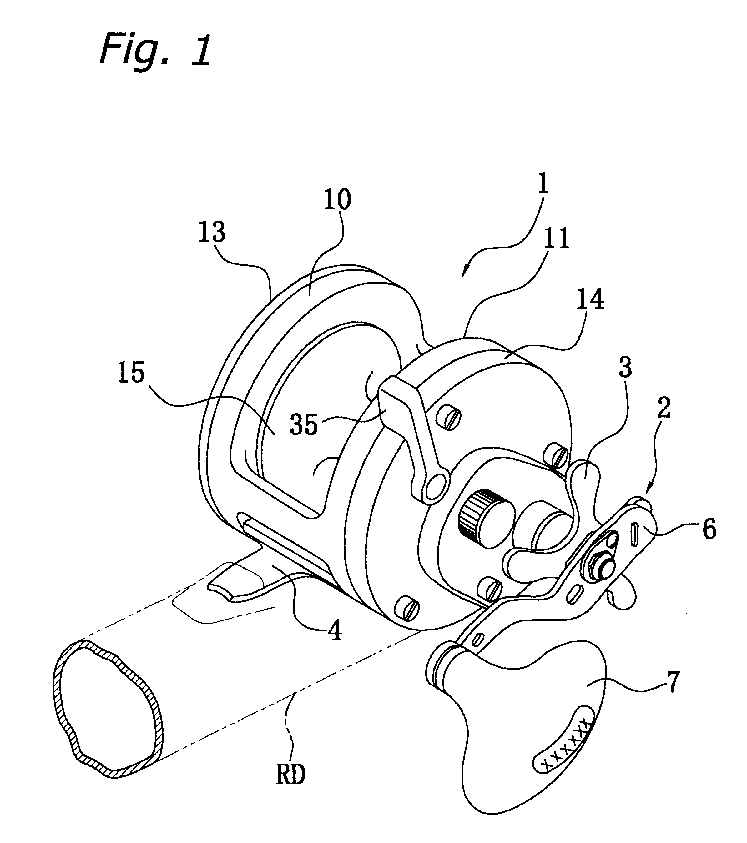
1. Technical FieldThe present invention relates to double bearing reels. More specifically, the invention relates to double bearing reels for attachment to fishing rods wherein fishing line is reeled in on an axis transverse to the fishing rod longitudinal direction.2. Description of Related ArtIn a double bearing reel, a fishing line is reeled in around an axis that crosses a longitudinal direction of a fishing rod. A double bearing reel includes a reel body, a handle, a spool, a rotation transmitting mechanism, a clutch mechanism, and a braking mechanism which is also referred to as a casting control mechanism. The reel body is attached to the fishing rod. The handle is rotatably disposed in the reel body. The spool, which is used for reeling in the fishing line, is rotatably supported on the reel body. The rotation transmitting mechanism transmits the rotation of the handle to the spool. The clutch mechanism is provided in the course of the rotation transmitting mechanism. The br...

Claims


Application Information

Patent Timeline
IPC IPC(8): A01K89/00A01K89/033A01K89/015
CPCA01K89/033A01K89/0179A01K89/0186A01K89/051A01K89/057
Inventor IKUTA, TAKESHI
Owner SHIMANO INC
Learn More