Modified surface for reducing the turbulences of a fluid and transportation process

a technology of fluid and transportation process, applied in the direction of fluid heaters, air-flow influencers, lighting and heating apparatus, etc., can solve the problems of large pressure drop, complex association, and device with fins of different heights not benefiting from alternation,

Inactive Publication Date: 2001-02-27
INST FR DU PETROLE
View PDF12 Cites 34 Cited by
  • Summary
  • Abstract
  • Description
  • Claims
  • Application Information

AI Technical Summary

Problems solved by technology

Such an association is however complex and bulky.
However, such a device with an alternation of fins of different heights does not benefit locally by an addition of the effects (turbulence attenuation) resulting therefrom.
During transportation, friction occurs between

Method used


Image

  • Modified surface for reducing the turbulences of a fluid and transportation process
  • Modified surface for reducing the turbulences of a fluid and transportation process
  • Modified surface for reducing the turbulences of a fluid and transportation process

Examples


Embodiment Construction

In order to allow better comprehension of the main characteristics of the structure according to the invention, the description given hereafter by way of non limitative example relates to the making of a pipe used to transport a pressurized natural gas from a production well to a processing site for example.

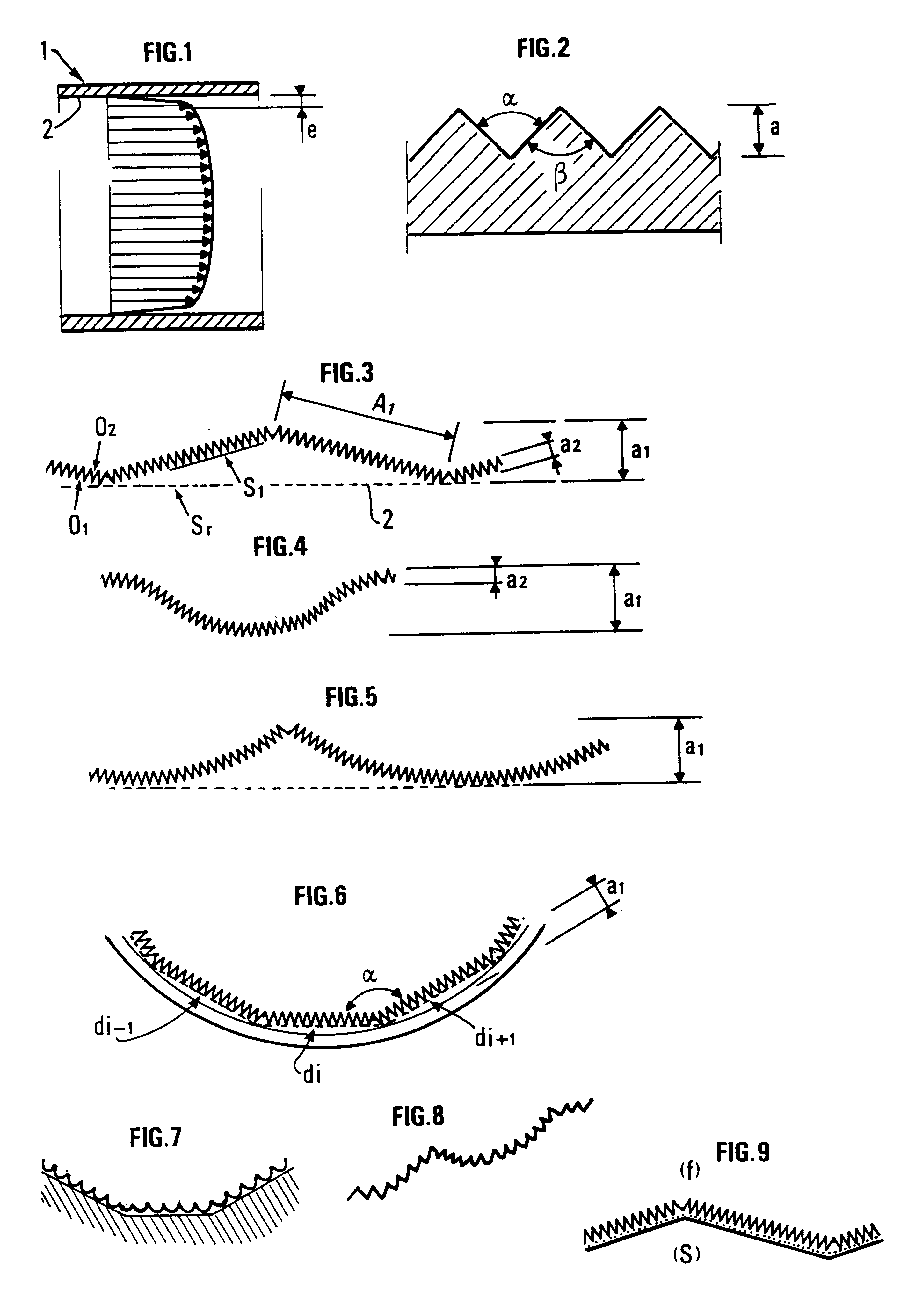
FIG. 1 shows the general shape of the velocity profile of a fluid flowing in a pipe 1, the fluid flow being a flow referred to as "turbulent".

Shearing for turbulent type flows is very high in a layer of relatively reduced thickness "e" and close to the inner wall 2 of pipe 1, the velocity field at the center of the flowing fluid being substantially uniform, unlike the velocity field observed in the boundary layer of thickness "e".

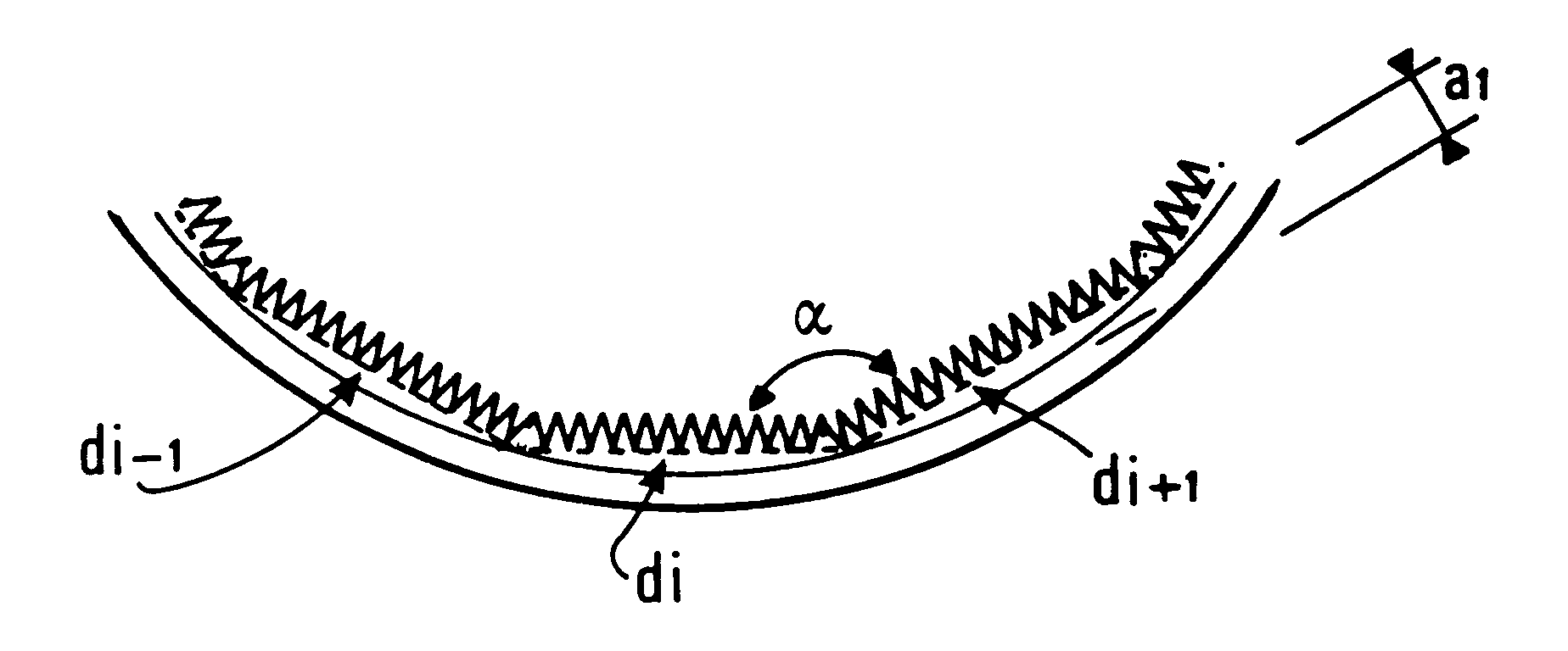
In order to limit the pressure drops resulting from the interaction between the fluid and the inner wall 2 of the pipe, the invention reduces the viscous dissipation effects linked with the turbulence in close vicinity of the wall, by using a structure e...


PUM


Abstract

The invention is a structure for inhibiting the turbulence phenomena of a fluid, exhibiting a surface geometry comprising at least one series of inhibition surfaces which inhibit turbulence present in a boundary layer of the fluid in proximity to the wall of the structure and which extend substantially longitudinally in the direction of flow of the fluid. The inhibition surfaces comprise at least a first series of surfaces (01) of amplitude a1 and at least a second series of surfaces (02) of amplitude a2. The second series of surfaces (02) is arranged so as to be superposed on the first series of surfaces (01), the first series of surfaces (01) allowing inhibition of at least turbulence of great amplitude and the second series of surfaces (02) allowing inhibition of at least turbulences of low amplitude. The structure has an application for forming at least part of a pipe for conveying a pressurized gas.

Description

1. Field of the InventionThe present invention relates to a structure having a surface which reduces turbulence problems existing within the boundary layer of a fluid moving with respect to the surface.2. Description of the Prior ArtThe prior art describes various structures for controlling phenomena due to the interaction of a boundary layer of a fluid in motion with respect to a surface and notably turbulence phenomena.These structures can be formed by surfaces provided with grooves present in the turbulence region. The axis of the grooves extends in the direction of flow of the fluid. The purpose of these grooves is to reduce the turbulence phenomena existing within the boundary layer of the fluid in motion and, by reducing friction between the surface and the fluid, to minimize pressure drops.Experiments described in the prior art indicate pressure drop decreases up to 7% for example.The grooves or pressure drop reduction means can have various geometries, and the number thereof...

Claims


Application Information

Patent Timeline
IPC IPC(8): B64C21/00B64C21/10F15D1/10F15D1/00
CPCB64C21/10F15D1/065Y02T50/166Y02T50/10
Inventor FALCIMAIGNE, JEANPALERMO, THIERRYROJEY, ALEXANDRE
Owner INST FR DU PETROLE
Why Eureka
Try Eureka