Fluid power gripper

a technology of power gripper and gripper body, which is applied in the direction of metal-working holders, supporters, positioning apparatuses, etc., can solve the problems of low friction loss, achieve low friction operation, simplify the design of small overall size of grippers, and reduce friction loss

Inactive Publication Date: 2001-03-13
FESTO AG & CO KG
View PDF5 Cites 16 Cited by
  • Summary
  • Abstract
  • Description
  • Claims
  • Application Information

AI Technical Summary

Benefits of technology

One object of the invention is to provide a gripper of the type initially mentioned which while having a simple structure is characterized ba low friction operation and which simplifies the design of small overall sizes of grippers.

Problems solved by technology

This means that the mesh engagement between the mesh means provided on the pistons and on the body of revolution extends along only an extremely small axial length of the receiving space, this leading to low friction losses.

Method used


Image

  • Fluid power gripper
  • Fluid power gripper
  • Fluid power gripper

Examples


Embodiment Construction

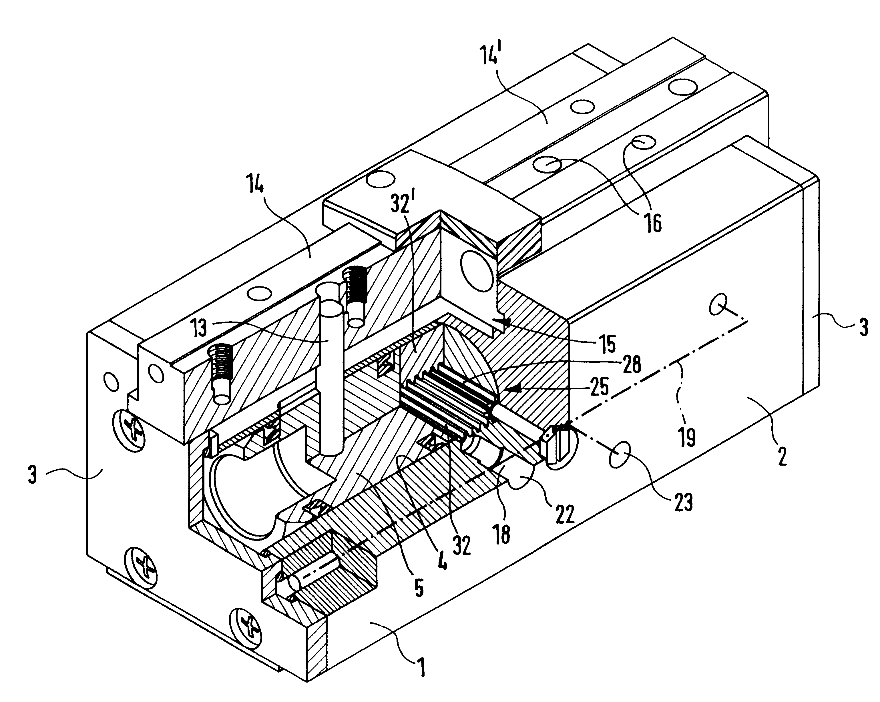
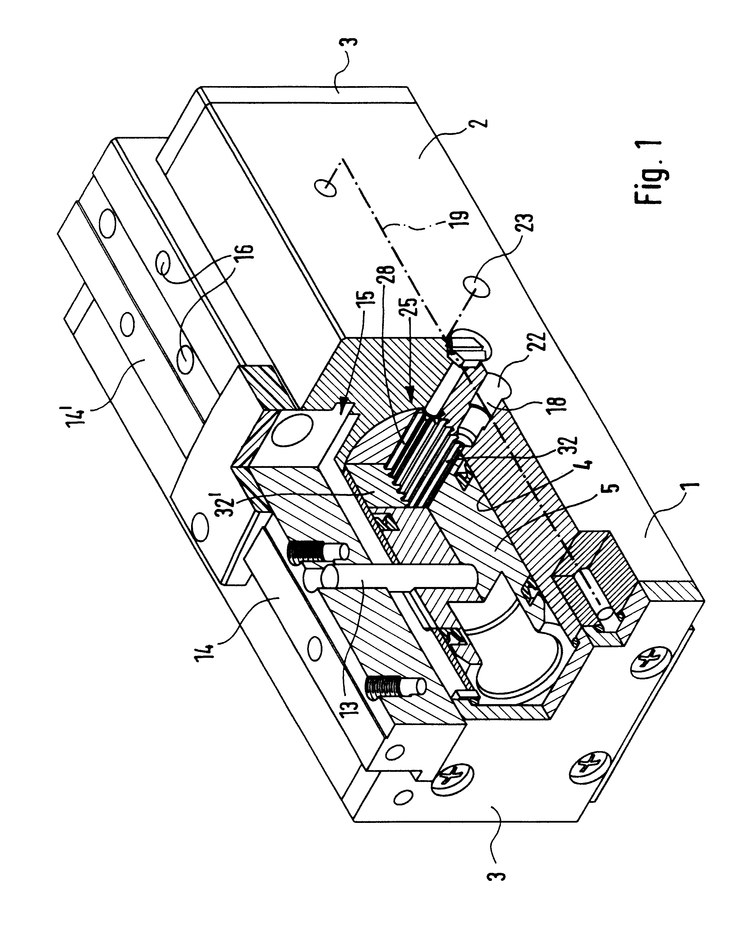
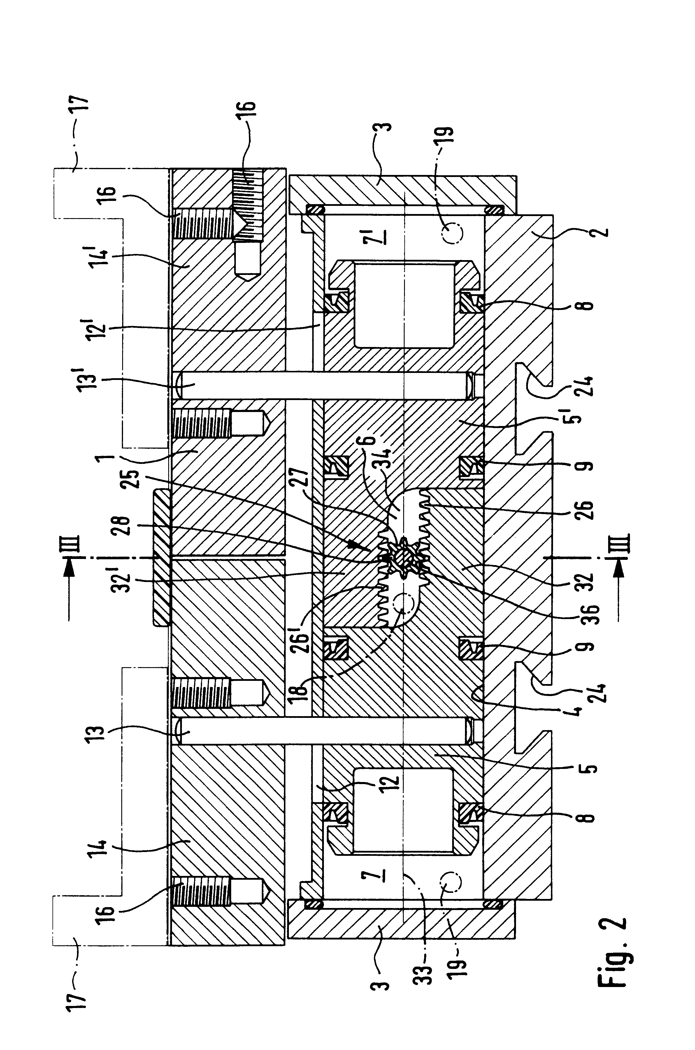
The fluid power gripper depicted in the drawings comprises a housing 1, which is for example in the form of a parallelopiped having a tubular center section 2, which at its ends is sealed in a fluid-tight fashion by end plates 3. In the housing a more particularly cylindrical longitudinal receiving space 4 is provided, wherein two pistons 5 and 5' are arranged in sequence for axial motion.

There is no separating wall between the two pistons 5 and 5'. Consequently the two pistons 5 and 5' jointly delimit an inner receiving space section 6 arranged between them. At the sides or end of a each piston 5 and 5' opposite to the inner space section there is a an outer receiving space section 7 and 7' which is on the one hand delimited by the associated piston 5 and 5' and on the other hand by the adjacent end plate 3.

Annular seals 8 and 9 on the outer periphery of each piston 5 and 5' are in sealing and sliding engagement with the inner face of the receiving space 4 and thus produce a fluid-...


PUM


Abstract

A fluid power gripper which contains a receiving space, in which two pistons are located able to be moved axially by fluid power in opposite drive directions, such pistons being kinematically coupled by a synchronization means. The synchronization means comprises first mesh means, which are provided on opposite mutually facing side surfaces of two mutually overlapping axial tails of the pistons. Furthermore the synchronization means comprises second mesh means provided on a body of revolution arranged between the two axial tails and having an axis of rotation extending athwart the longitudinal axis of the receiving space.

Description

The invention relates to a fluid power gripper comprising a housing having a receiving space in which two pistons are located able to be moved by fluid power to perform oppositely directed axial drive movements, which pistons are connected or adapted to be respectively connected with a gripper element, a synchronization means, including a body of revolution, for synchronization of the drive movements of the two pistons, such synchronization means having first mesh means, provided on the two pistons, and second mesh means simultaneously in engagement with the first mesh means, such second mesh means being provided on the body of revolution, and axial tails provided on the two adjacent end regions of the two pistons, such axial tails overlapping one another axially and being opposite to each other with a clearance athwart the longitudinal axis of the receiving space, such tails furthermore bearing, on facing lateral surface thereof, the first mesh means, the body of revolution bearing...

Claims


Application Information

Patent Timeline
Patent Type & Authority Patents(United States)
IPC IPC(8): B25J15/02F15B15/08F15B15/00
CPCB25J15/0253F15B15/065
Inventor BELLANDI, GIUSEPPEMAFFEIS, GIUSEPPE
Owner FESTO AG & CO KG
Why Eureka
Try Eureka