
Forceps stopper for endoscope

a technology of endoscope and forceps, which is applied in the field of forceps stoppers for endoscopes, can solve the problems of flexible tubes, no longer functional, and insufficient stiffness of tubes,

Inactive Publication Date: 2001-03-13
ASAHI KOGAKU KOGYO KK
View PDF14 Cites 92 Cited by
  • Summary
  • Abstract
  • Description
  • Claims
  • Application Information

AI Technical Summary

Benefits of technology

According to a third aspect of the present invention, there is provided a forceps stopper according to the first aspect of the present invention, wherein the surface of said annular seal member has a coating layer with low frictional resistance.

Problems solved by technology

On the other hand, the flexible tube does not have enough stiffness so that the flexible tube would bend by pass resistance thereof and become no longer functional when the treatment tool is passed through the slit formed in the seal member of the forceps stopper.
This problem cannot be completely solved by use of the slit or other closure forming means because if the slit or the like is not formed which can be tightly closed, it is afraid that a pressure leakage would occur at an inlet of a channel through which the treatment tool is inserted.
In various seal members used today, the pressure leakage easily occurs in a seal member formed by rubber sheets having a slit formed across their thickness.

Method used


Image

  • Forceps stopper for endoscope
  • Forceps stopper for endoscope
  • Forceps stopper for endoscope

Examples


Embodiment Construction

The present invention will now be described with reference to the accompanying drawings.

In FIG. 12, a treatment tool 10 has been inserted into a channel 4. An inserting portion 1 of the endoscope has a basal end connected to a control part 2 and a forceps stopper 3 is mounted on an inlet of the control part 2 from which the channel 4 extends toward the inserting portion 1.

A sheath 11 of the treatment tool 10 inserted into the channel 4 has a distal tip 11a projecting forward from the distal end of the inserting portion 1 of the endoscope. A reference numeral 12 shows a hand operated control part connected to the basal end of the sheath 11.

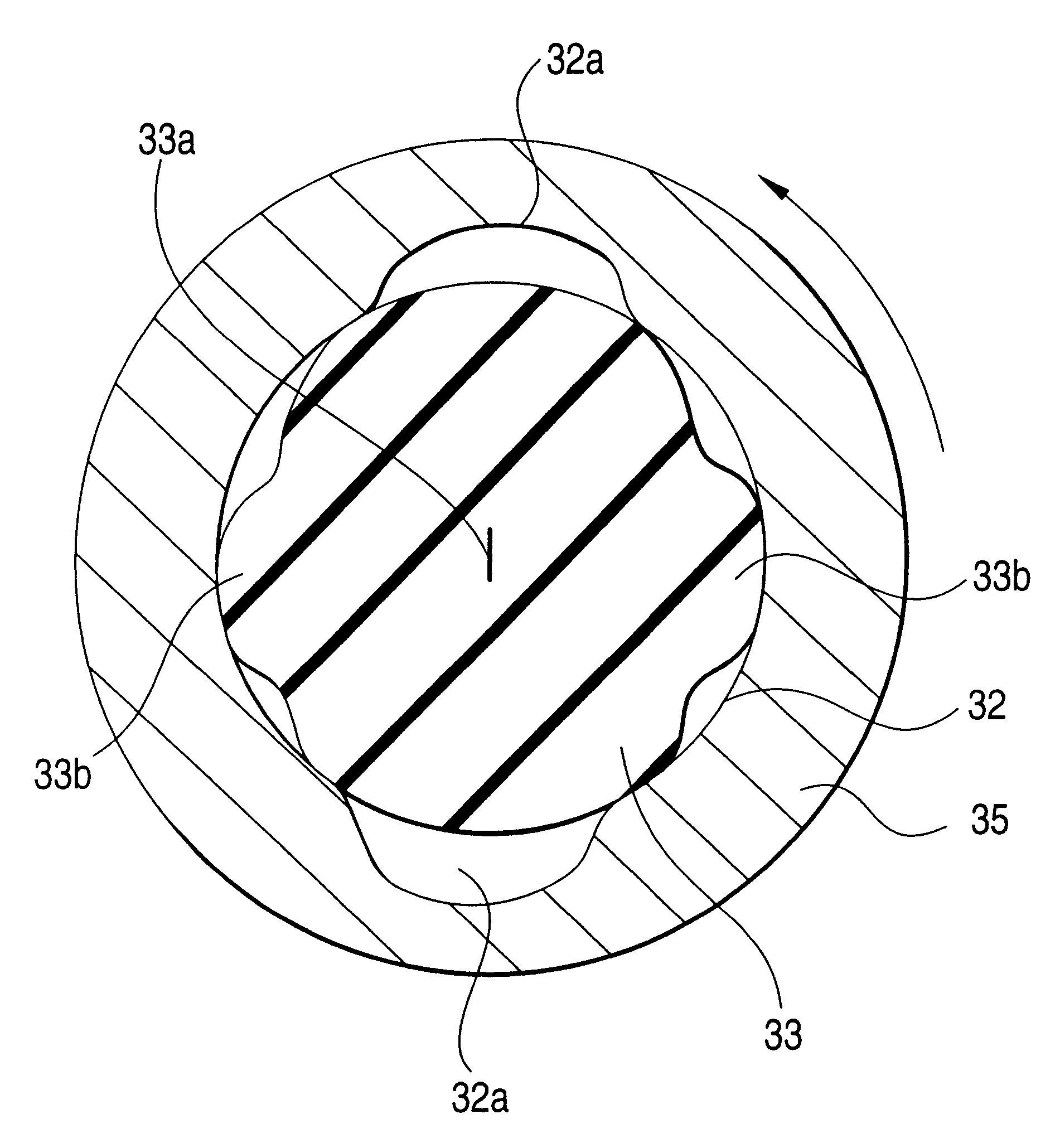
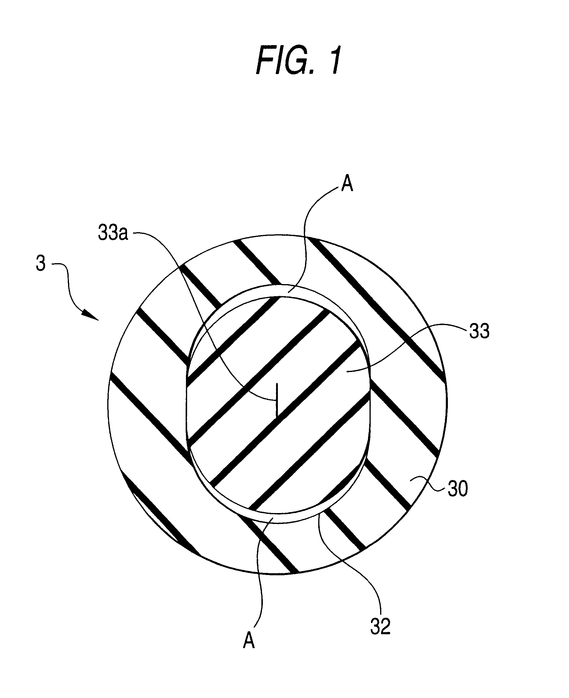
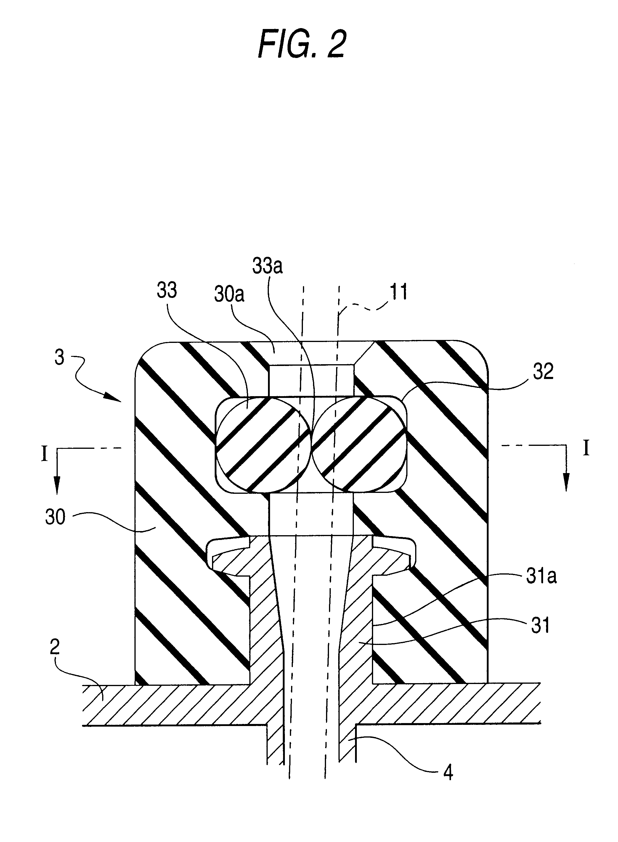
FIG. 2 shows a longitudinal section of the forceps stopper 3 and FIG. 3 shows a longitudinal section in view of another side. A reference numeral 31 is the treatment tool receiving socket that communicates with the channel 4 to project from the surface of the control part 2. The socket 31 is shaped like a so-called "lure lock" male socket.

A referen...


PUM


Abstract

A forcep stopper of an endoscope includes an annular seal member disposed on an inlet of a channel through which a treatment tool is inserted. The forcep stopper has a circular hole whose diameter is dimensioned to be smaller than an outer diameter of a sheath of the treatment tool. The stopper is made of an elastic material such that the hole expands when the treatment tool passes through the hole. Further, a squeeze member is provided for inwardly squeezing the annular seal member from opposite lateral sides of the annular seal member in such a manner that the hole is tightly closed.

Description

1. Field of the InventionThe present invention relates to a forceps stopper for an endoscope for preventing a pressure leakage from an inlet of a channel through which a treatment tool is inserted.The present disclosure relates to the subject matter contained in Japanese Patent Application No. Hei. 10-66521 filed on Mar. 17, 1998, which is incorporated herein by reference in its entirety.2. Description of the Related ArtA forceps stopper of an endoscope usually has a seal member that is an elastic material, in which a closure such as a slit or the like is formed so that the closure can be spread open by means of a treatment tool to be inserted into the closure. The seal member can assume many and diverse shapes.The treatment tools inserted into the forceps stopper for the endoscope include a forceps, a snare, a syringe, a basket and a contrast medium supply tube and the like. Such treatment tools are roughly classified into two groups, in which one uses a metallic coil pipe as a sha...

Claims


Application Information

Patent Timeline
Patent Type & Authority Patents(United States)
IPC IPC(8): A61B17/34A61B1/012A61B1/018A61B1/00
CPCA61B1/00137A61B1/018A61B17/3462A61B17/3498A61B2017/347
Inventor OUCHI, TERUO
Owner ASAHI KOGAKU KOGYO KK
Learn More