Compressing device for pneumatic massager

a compression device and massager technology, applied in the field of compression devices for pneumatic massagers, can solve the problems of increasing the cost of the massager, requiring the user to incur difficulty in bending the joints, and prolonging the time for attachmen

Inactive Publication Date: 2001-03-20
NITTO KOHKI CO LTD
View PDF5 Cites 96 Cited by
  • Summary
  • Abstract
  • Description
  • Claims
  • Application Information

AI Technical Summary

Problems solved by technology

Particularly, the distributors tend to boost the cost of the massager because of their complicated structure.
Further, the conventional compressing bag, when attached to a leg or an arm, inevitably covers the joints of the leg or arm and compels the user to incur difficulty in bending the joints.
In this case, the number of sites of attachment are increased, the time spent for attachment is longer, and the number of component parts is increased, possibly causing additions to the cost of the massager itself.
A distributing valve intended to handle compressed air is expensive as mentioned above, because of its complicated structure, and poses the problem of inevitably boosting the cost of the pneumatic massager.

Method used


Image

  • Compressing device for pneumatic massager
  • Compressing device for pneumatic massager
  • Compressing device for pneumatic massager

Examples


Embodiment Construction

Preferred embodiments of the compressing device for a pneumatic massager according to this invention will be described below with reference to the accompanying diagrams.

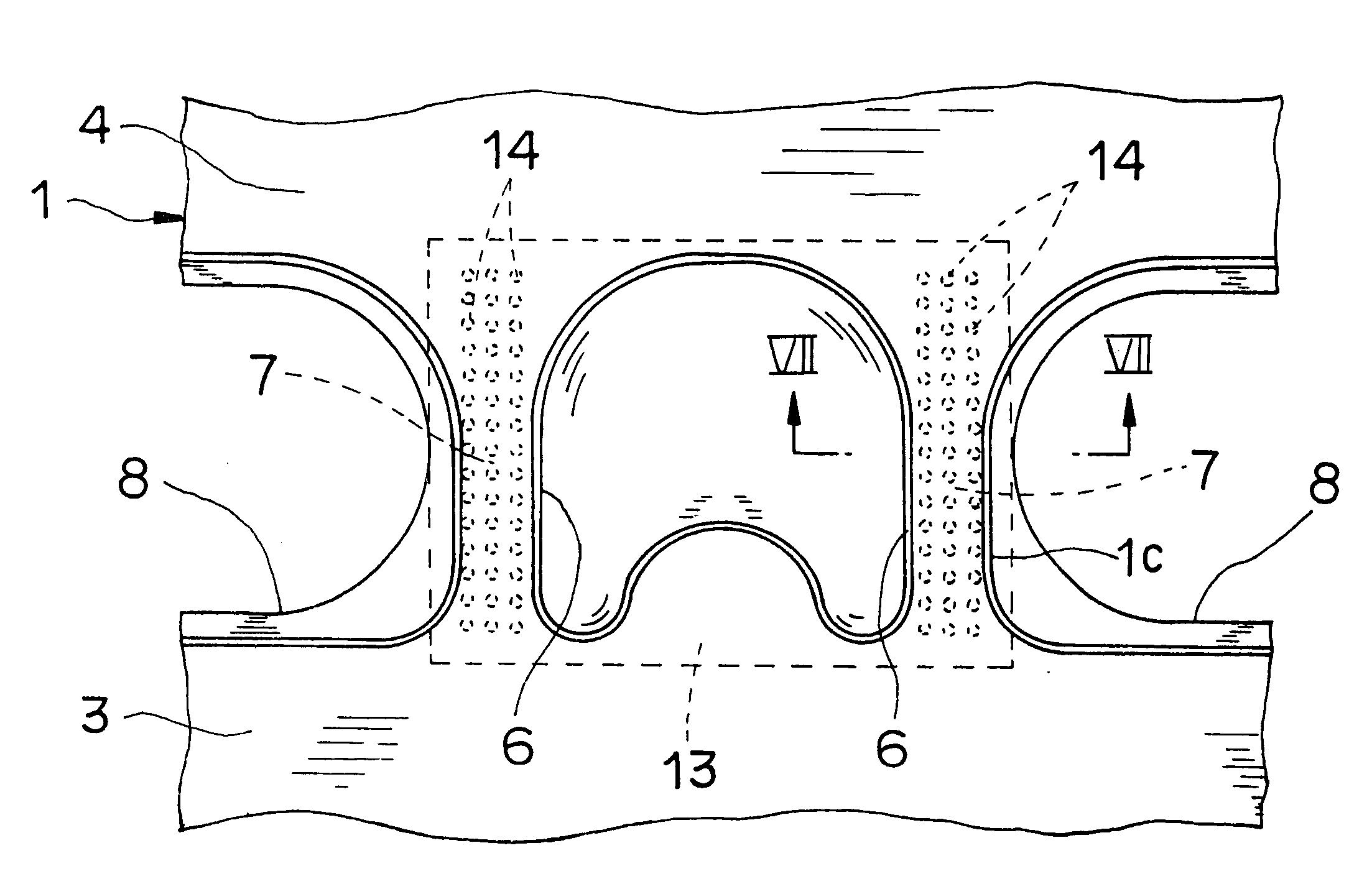
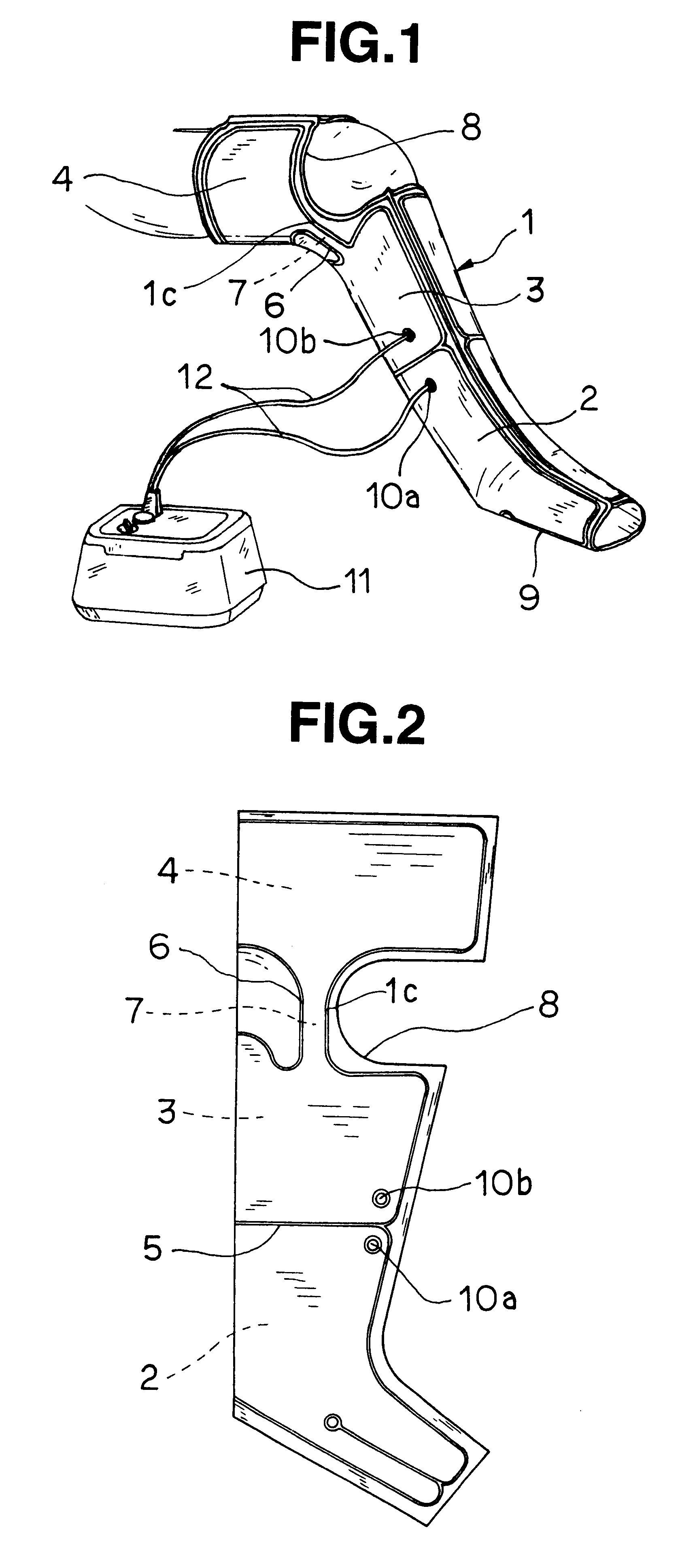
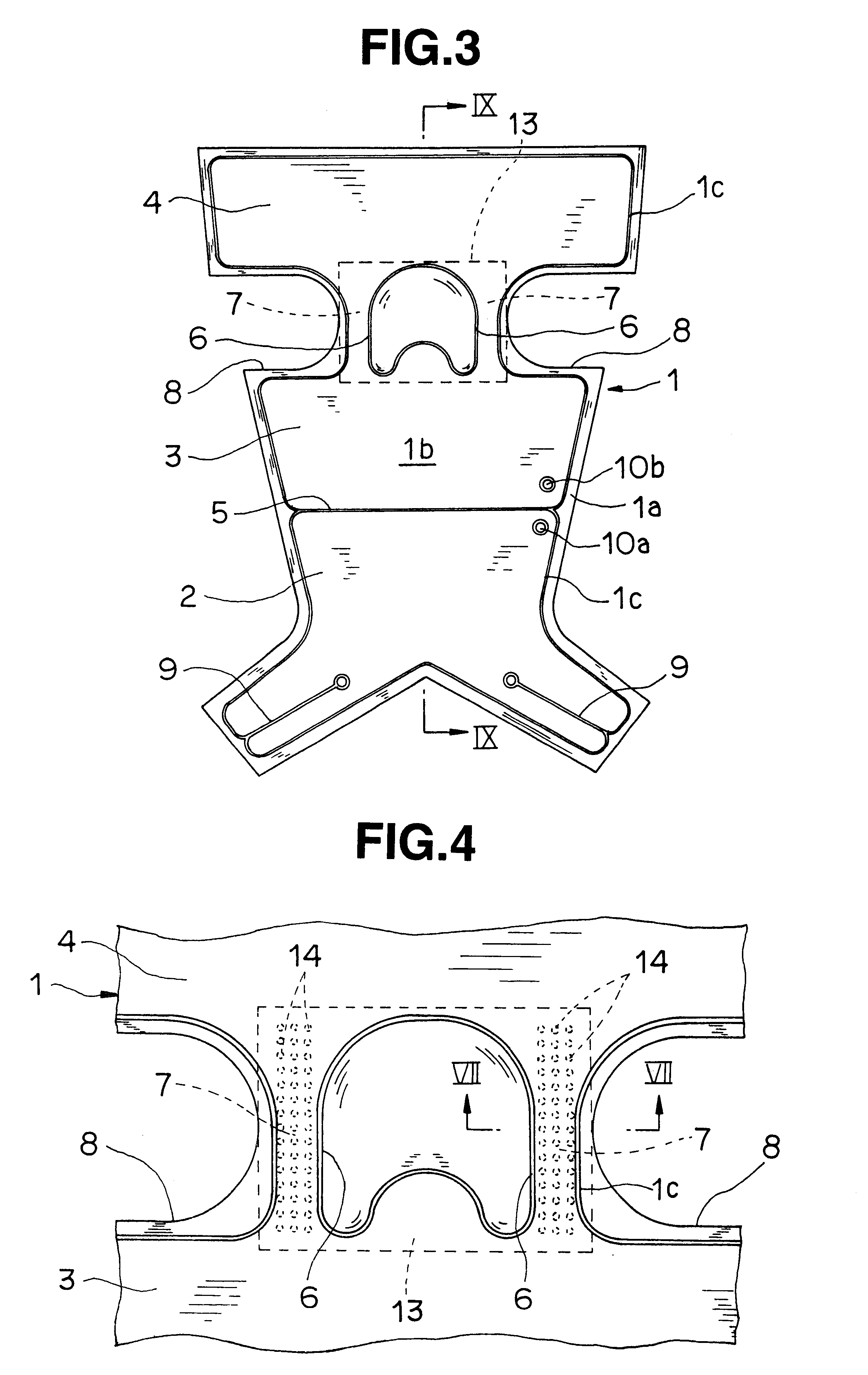
A bag body 1 is produced by forming an outer air-impervious resin sheet 1a of small elasticity and an inner air-impervious resin sheet 1b of large elasticity in such a shape as illustrated in FIG. 3 and FIG. 9 and fusing the matched peripheries as by a high-frequency heating means.

As the raw material for these sheets 1a and 1b, a synthetic resin such as urethane resin or polyvinyl chloride resin is used.

Two sheet members formed roughly in the shape of a leg and containing notches 8 in the approximate shape of the letter U at the knee position as illustrated in FIGS. 1 through 3 are superposed, and the matched peripheries of the sheet members are fused at 1c by the use of a high-frequency heating means, for example, to obtain one bag body 1. The sheet members are then fused in a short width direction to form a sealed ...


PUM


Abstract

A compressing device for a pneumatic massager includes a bag body formed of a plurality of airtight cells with sealed portions for separating the airtight cells and adapted to inflate and contract the airtight cells by supplying and discharging compressed air to and from the bag body. At least one of the airtight cells is provided with a port for supplying and discharging compressed air. The bag body is provided with a communicating path allowing communication between the at least one airtight cell and the airtight cells lacking the port.

Description

1. Field of the InventionThis invention relates to a compressing device for a pneumatic massager, which is provided with a plurality of airtight cells adapted to be inflated and contracted by the supply and discharge of compressed air.2. Description of the Prior ArtA conventional compressing device for a pneumatic massager generally has a plurality of airtight cells arranged parallel so as to form a compressing bag with a sheetlike wall and permits the massager to be used by having the compressing bag wrapped fast around an arm or a leg.In this case, the compressing bag, to which compressed air inlets and outlets and compressed air sources disposed in the airtight cells are connected via air hoses, produces a massaging action by inflating and contracting the airtight cells sequentially in the direction from the peripheral to the central side by effecting the supply and discharge of compressed air in the relevant airtight cells.The massager of this construction, therefore, requires a...

Claims


Application Information

Patent Timeline
Patent Type & Authority Patents(United States)
IPC IPC(8): A61H23/04
CPCA61H9/0078
Inventor TAKEUCHI, HIROSATOMATSUMURA, MITSUMA
Owner NITTO KOHKI CO LTD
Why Eureka
Try Eureka