Method for manufacturing intraluminal device

a manufacturing method and technology for intraluminal devices, applied in the direction of blood vessels, prostheses, catheters, etc., can solve the problems of extremely small diameter and flexible catheters, extremely difficult to fabricate these devices, and high cost of laser machining

Inactive Publication Date: 2001-03-20
EV3 PERIPHERAL +1
View PDF8 Cites 172 Cited by
  • Summary
  • Abstract
  • Description
  • Claims
  • Application Information

AI Technical Summary

Problems solved by technology

Many such designs require extremely small diameter and flexible catheters.
Since intraluminal devices have such small diameters, it is extremely difficult to fabricate these devices.
Laser machining is very costly as well as presenting other problems.
Even though the laser is not being used to remove metal, the use of a laser is still required to remove the coating.
Such a use is complicated, costly and difficult to control.
While the '429 patent represents a significant advance in the production of stents and catheters, chemical etching presents certain challenges.
For example, when a chemical etchant is applied to a limited exposed area on the exterior of a tube, the etchant does not dissolve perfectly radially toward the center of the tube.
For example, intricate, narrow corners are difficult to form in stents and catheters made by chemical etching.
Further, the non-radial etching path can result in the formation of stent or catheter walls being non-radial relative to the tube's axis.
Such edges are undesirable and require further process.

Method used


Image

  • Method for manufacturing intraluminal device
  • Method for manufacturing intraluminal device
  • Method for manufacturing intraluminal device

Examples


Embodiment Construction

Referring now to the several drawing figures in which identical elements are numbered identically throughout, a description of a preferred embodiment will now be provided. In providing such a description, specific processes will be described. It will be appreciated that variants (some of which will be later described) of such specifics are intended to be included within the scope of the appended claims.

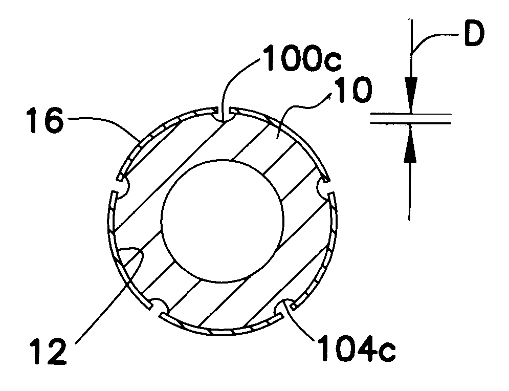
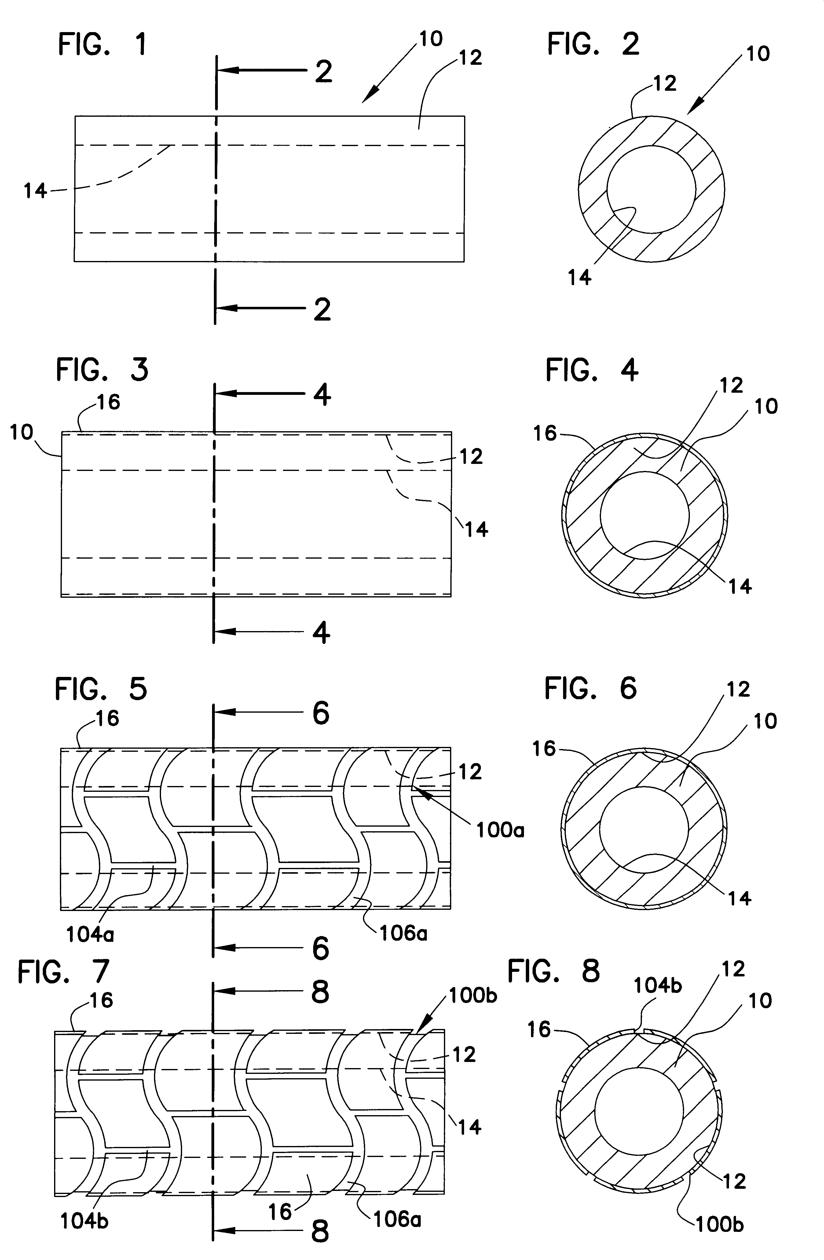
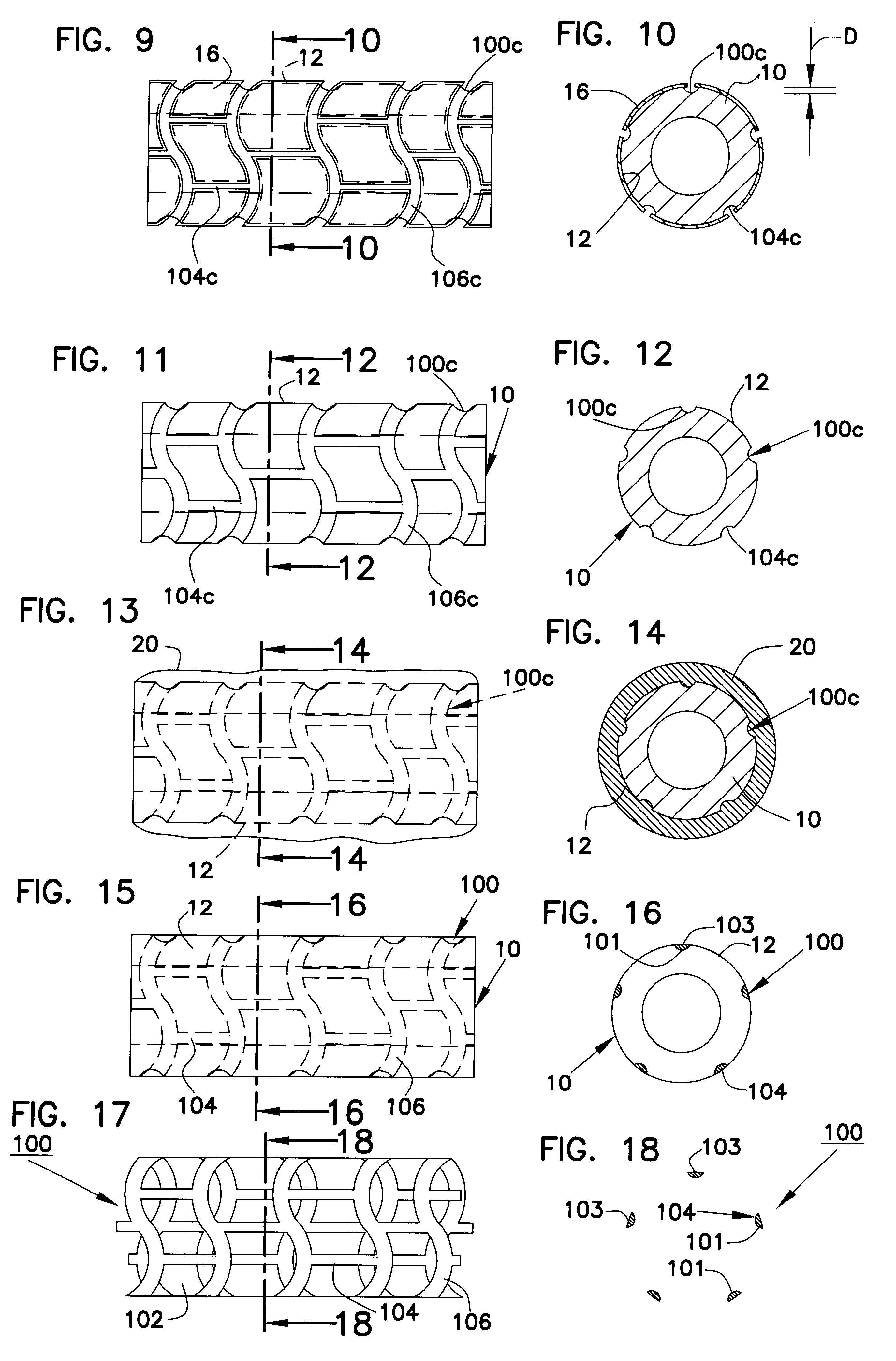
Referring to FIGS. 1-2, a metal tube 10 is shown for use as a mandrel in forming a tubular intraluminal device according to the present invention. For ease of illustration, the present invention will be described for making a stent 100 (shown in FIGS. 17-18) but is also applicable to the manufacture of other tubular intraluminal devices (e.g., catheters).

By way of example, the stent 100 is a reticulated tube of about 0.050 inch (about 1.25 mm) outside diameter, 0.75 inch (about 19 mm) length and 0.005 inch (about 0.13 mm) wall thickness. It will be appreciated the recitation of such d...


PUM

PropertyMeasurementUnit
wall thicknessaaaaaaaaaa
lengthaaaaaaaaaa
lengthaaaaaaaaaa

Abstract

A generally tubular device (e.g., a stent or catheter) for placement in a lumen of a patient's body is made by forming a depressed pattern in an external surface of a mold. The depressed pattern corresponds to a desired shape of the generally tubular device. A material is deposited in the depressed pattern for the material to form the generally tubular device conforming to the depressed pattern. The generally tubular device is separated from the mold.

Description

1. Field of the InventionThis invention pertains to tubular intraluminal devices (such as stents or catheters) for placement in a lumen of a patient's body. More particularly, this invention pertains to a method for manufacturing such devices.2. Description of the Prior ArtIntraluminal devices for placement in a lumen of a patient are widely used. For example, stents are commonly used to treat obstructed coronary arteries. Typically, such stents are reticulated tubular structures. The stents are placed on a balloon tip catheter and advanced through the patient's blood vessels to an occluded artery. At the occluded site, the balloon is expanded to enlarge the stent's diameter. With the stent so enlarged, the balloon is deflated and the catheter is removed from the patient leaving the enlarged stent in place with the intent that the formerly occluded site is held patent by the stent.In addition to advancing stents as described above, catheters are used in a wide variety of application...

Claims


Application Information

Patent Timeline
Patent Type & Authority Patents(United States)
IPC IPC(8): A61F2/06A61M25/00B29D23/00A61F2/90
CPCA61F2/91A61F2/915A61M25/0009A61M25/0013B29D23/001A61F2002/91533A61F2002/9155B29L2031/7542Y10S623/901
Inventor CLUBB, ELIZABETH A.CLUBB, THOMAS L.DONADIO, III, JAMES V.
Owner EV3 PERIPHERAL
Why Eureka
Try Eureka