
Agitator with adjustable magnetic drive coupling

a magnetic drive and agitator technology, applied in the direction of mixers, chemistry apparatus and processes, mixing, etc., can solve the problems of affecting the operation of the operator

Inactive Publication Date: 2001-03-27
MIXEL
View PDF28 Cites 90 Cited by
  • Summary
  • Abstract
  • Description
  • Claims
  • Application Information

AI Technical Summary

Benefits of technology

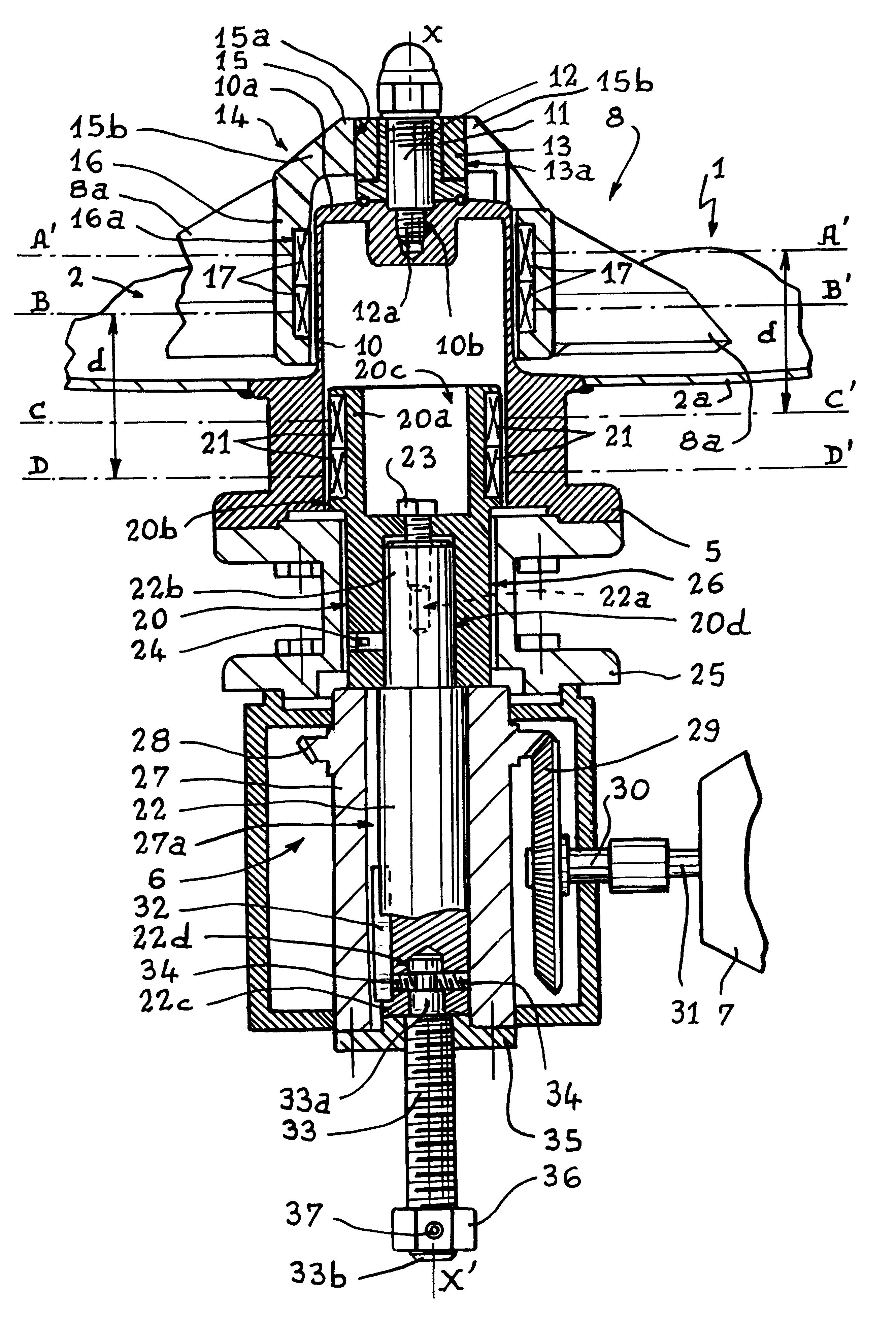
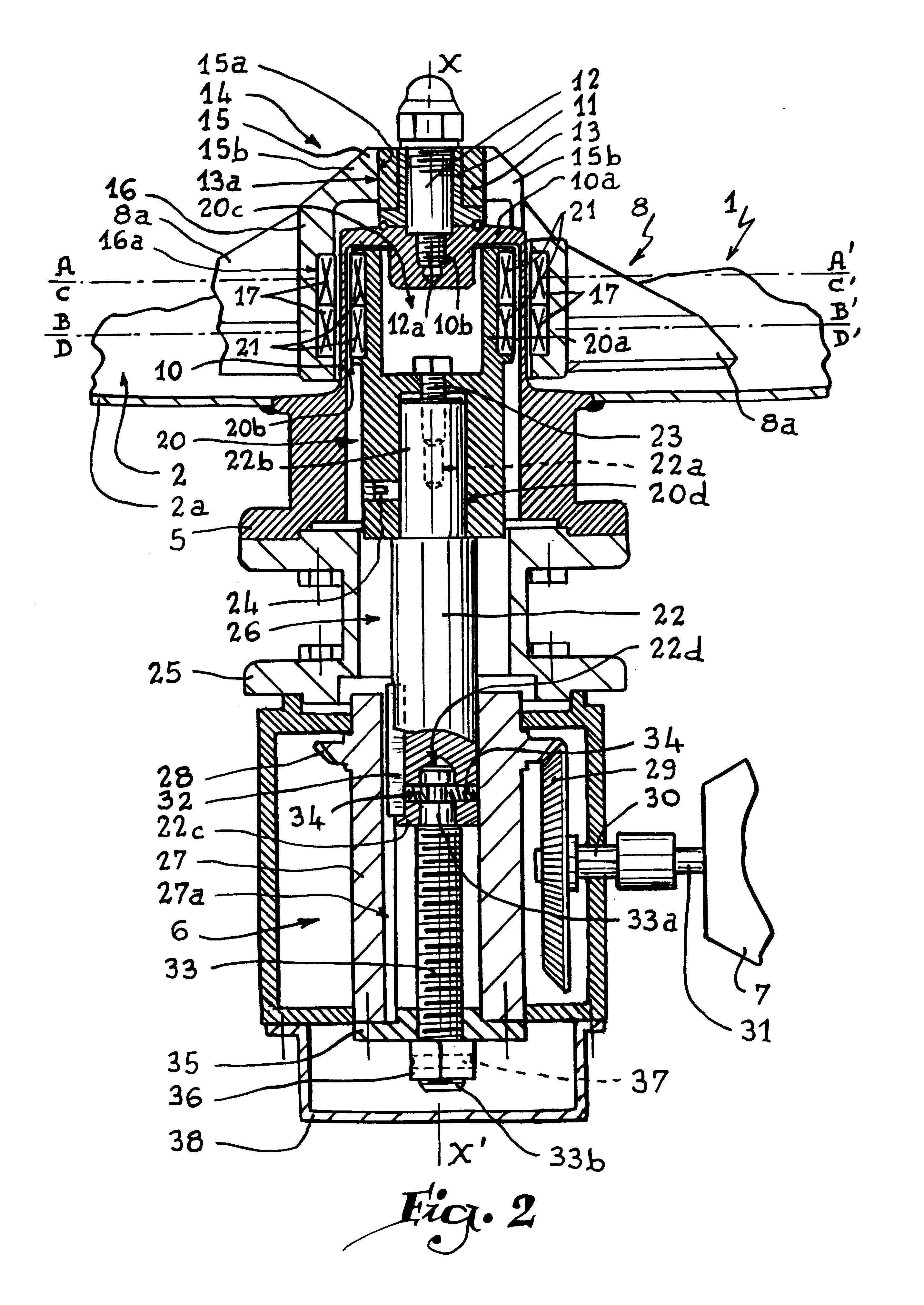
Thanks to the fact that the rotor is movable in translation, it may be retracted during the operations of assembly and dismantling of the propelling screw, so that the magnetic coupling means that it supports, such as permanent magnets, is spaced apart from the coupling means which equip the propelling screw by a distance sufficient to avoid the magnetic force between these coupling means disturbing the assembly or dismantling of the propelling screw. Displacement of the rotor inside the sleeve occurs in a direction corresponding to the shear of the air gap between the magnetic coupling means, i.e in practice between the permanent magnets respectively associated with the rotor and the propelling screw. Such shear perpendicular to the magnetic force created between these magnets does not require exerting a considerable effort insofar as this magnetic force does not oppose this shear. In other words, the magnetic coupling between the magnets of the rotor and of the propelling screw is nullified without this magnetic coupling greatly opposing the translation of the rotor. During assembly or re-assembly of the propelling screw, it suffices to place the latter on the sleeve, then to move the rotor in translation inside the sleeve until the magnets that it carries are opposite the magnets carries by the propelling screw. The invention therefore allows the propelling screw to be placed in position without interference with the magnets of the rotor, then to displace the rotor until it can drive the propelling screw, such displacement being effected in a direction such that it is unnecessary to overcome an intense magnetic force.
According to another advantageous aspect of the invention, the rotor and / or the drive shaft are adapted to be immobilized, in their movement of translation parallel to the axis, in an intermediate position between the first and second positions. This aspect of the invention makes it possible to use the agitator while the magnetic coupling effort between the rotor and the propelling screw is reduced with respect to the position where the respective coupling means are opposite, with the result that the drive couple of the propelling screw is limited. This is advantageous when it is desired to use the agitator with a mixture whose viscosity is variable, for example due to a chemical reaction. In that case, the agitator is blocked when the viscosity of the mixture is such that the couple which can be transmitted to the propelling screw is less than that which would be necessary to set it in motion in the mixture.
According to another advantageous aspect of the invention, the drive shaft is mounted to slide inside a hollow driven shaft of a reduction gear, these drive shaft and hollow shaft being corrected in rotation. Reduction gear is understood to mean any device for transmitting a movement of rotation, whatever its reduction ratio. In particular, it may be a bevel gear of ratio 1 / 1. The hollow shaft may be provided to bear a nut whose inner thread is adapted to cooperate with an outer thread of a threaded rod secured to the drive shaft. This makes it possible to create a nut and endless screw system for adjusting the position of the drive shaft and of the rotor in translation. The threaded rod is advantageously provided, at one of its ends projecting outside the hollow shaft, with means for controlling its rotation about its axis. In that case, a cap for protecting this end of the threaded rod and these control means may be provided, such cap being removably mounted on the reduction gear.

Problems solved by technology

Now, it is sometimes necessary to proceed with dismantling of the propelling screw, in particular for reasons of maintenance or inspection of the recipient in which the mixture is formed.
The magnetic forces necessary for driving the propelling screw of an industrial agitator are such that the effort that an operator must exert to remove the propelling screw is considerable, as this effort must overcome both the weight of the propelling screw and the force of magnetic coupling necessary for the drive.
This is even more critical when the propelling screw is replaced in position, insofar as, when it is being installed offered, it may happen that the magnetic effort is so intense that the propelling screw escapes the operator's grip and is violently applied against its support, consequently damaging the bearings and even injuring the operator.
In addition, it is particularly delicate for an operator to place the propelling screw in perfect alignment with the axis of rotation of its rotor, with the result that, if the propelling screw escapes the operator's grip due to the magnetic force that it undergoes, it tends to be applied aslant on its support, which may lead to the destruction of one of its blades, to the marking of the inner surface of the tank and / or to one of the bearings being damaged.
Such an approach requires that an operator manipulate heavy and cumbersome parts, these parts generally being located under the manufacturing tanks or recipients and being difficult to access.
In addition, such a dismantling of these drive systems must be followed by re-assembly during which the axes of the rotating parts must be very precisely aligned, which is not always possible taking into account the difficult access to the zones of re-assembly of the motor and its possible reduction gear.
Taking into account the small clearance present around the rotor, these impurities may lead to a machining of the magnets and to a blockage of the agitator.

Method used


Image

  • Agitator with adjustable magnetic drive coupling
  • Agitator with adjustable magnetic drive coupling
  • Agitator with adjustable magnetic drive coupling

Examples


Embodiment Construction

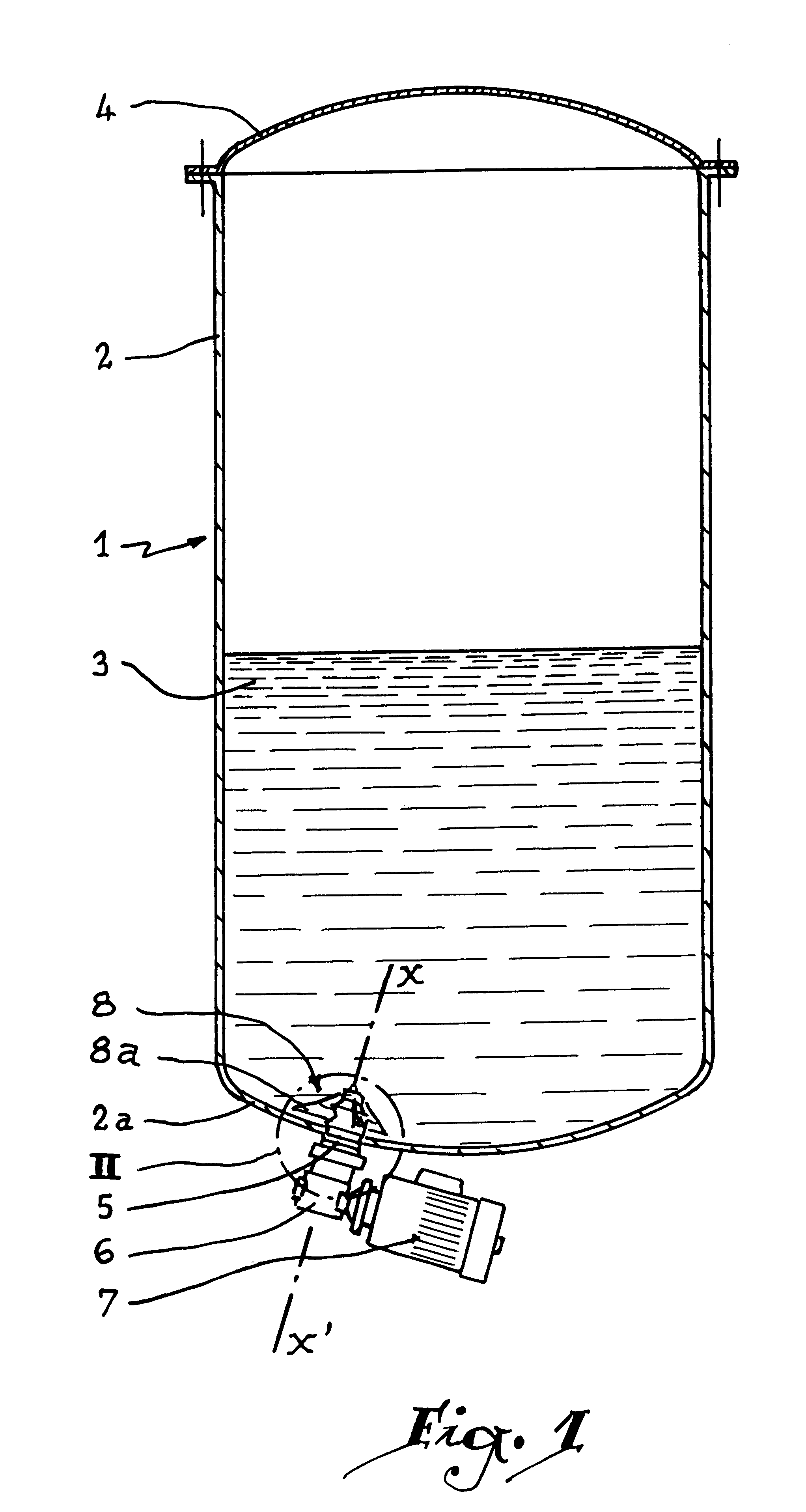
Referring now to the drawings, FIG. 1 shows a recipient 1 formed by a tank 2 and containing a mixture 3, while a lid 4 is provided to obturate an upper opening of the tank.

In the bottom wall 2a of the tank 2 is disposed a flange 5 made of a magnetic material supporting a reduction gear 6 and an electric motor 7, located outside the tank 2. A propelling screw 8 is arranged inside the tank 2, in the mixture 3. The rotation of the propelling screw 8 by the motor 7 results in a displacement of its blades 8a, of which two are visible in the Figures, around an axis of rotation X-X', which has the effect of stirring the mixture 3.

The flange 5 forms a blind or hollow sleeve 10 which extends inside the tank 2. A bearing 11 is mounted on the end 10a of the sleeve 10 thanks to a pin 12 whose threaded end 12a is received in a tapping 10b of the end 10a of the sleeve 10. The bearing 11 supports a bush 13 of which the outer surface 13a constitutes a bearing surface. The propelling screw 8 compris...


PUM


Abstract

A magnetically driven agitator which includes a member adapted to be mounted through a wall of a receptacle and which has a sleeve in which is housed a rotor which supports a first magnetic coupling structure. A propelling screw is disposed around the sleeve and supports a second magnetic coupling structure which cooperates with the first magnetic coupling structure in order to rotate the screw about an axis of rotation. The rotor is moveable parallel to the axis of rotation inside the sleeve between a first position where the first and second coupling structures are generally opposite to provide a maximum magnetic force therebetween to selected second positions where the magnetic force between the first and second coupling structures is varied such that the magnetic force may be reduced or substantially eliminated.

Description

1. Field of the InventionThe present invention relates to a magnetically driven agitator and to a process for adjusting the couple limiting transmission of effort of such an agitator.2. Brief Description of the Related ArtAgitators are conventionally used for stirring a mixture contained inside a recipient in order to avoid decantation or any other alteration of the mixture in the course of time. A magnetically driven agitator has the advantage that the propelling screw which it comprises is set in motion by a magnetic coupling which occurs without physical contact between two rotating parts of which one is driven by the driven shaft of an electric motor while the other is constituted by a propelling screw. This makes it possible to arrange the part associated with the shaft of the electric motor outside the recipient while the propelling screw is installed inside the recipient. Any danger of leakage at the level of the agitator may thus be set aside. This is particularly useful whe...

Claims


Application Information

Patent Timeline
Patent Type & Authority Patents(United States)
IPC IPC(8): B01F13/08B01F13/00
CPCB01F13/0827B01F33/4535B01F33/453
Inventor EYRAUD, PHILIPPEFLAVIEN, GUY
Owner MIXEL
Features
  • Generate Ideas
  • Intellectual Property
  • Life Sciences
  • Materials
  • Tech Scout
  • Unparalleled Data Quality
  • Higher Quality Content
  • 60% Fewer Hallucinations
Learn More