Endoscopic instrument which can be bent

Inactive Publication Date: 2001-03-27
KARL STORZ GMBH & CO KG
View PDF6 Cites 103 Cited by
  • Summary
  • Abstract
  • Description
  • Claims
  • Application Information

AI Technical Summary

Problems solved by technology

The instruments known from the aforementioned prior art documents present the disadvantage that either the distal end is not bendable over a wide field of traverse, or that the instruments require a comparatively substantial space because a single linearly displaceable actuator travels a substantial axial distance in order to pivotally displace the bendable end in a desirable position.
As a result, these instruments are

Method used


Image

  • Endoscopic instrument which can be bent
  • Endoscopic instrument which can be bent
  • Endoscopic instrument which can be bent

Examples


Embodiment Construction

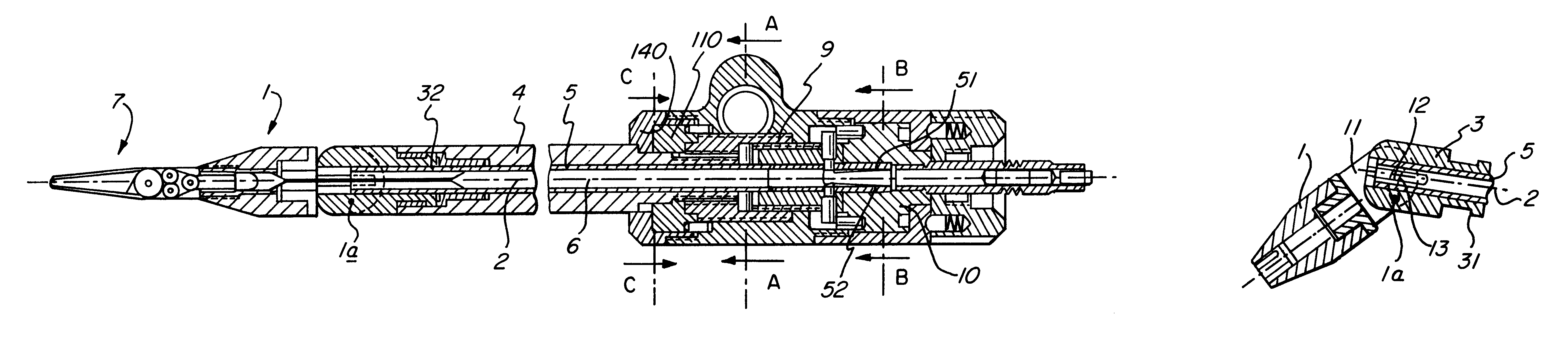
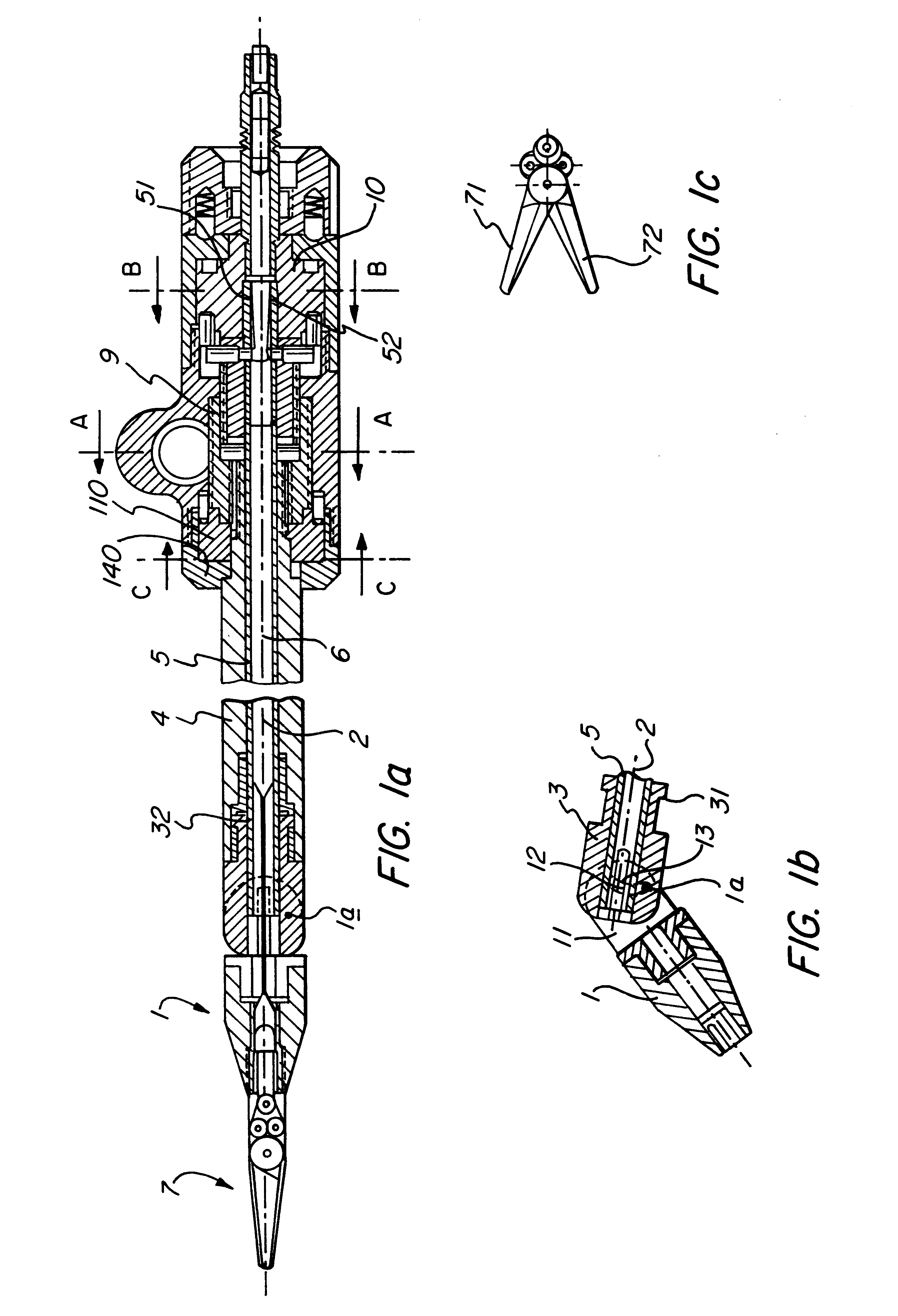
An endoscopic instrument illustrated in FIG. 1 includes coaxially positioned an external tube 4 and an internal hollow cylinder 5 which extend along a center axis 2. As will be explained in detail hereinbelow, opposite axial displacement of the tube and the cylinder causes the distal end 1 of the instrument to move axially and rotatably to bring an engaging element 7 in at least one angular position, as shown in FIG. 1b.

Particularly, the distal end 1 includes a pivoting element 11 formed with a curved groove 12 and a bayonet flange 31, which detachably engages a bayonet socket 32 of the external tube 4 for axial displacement therewith. Due to the bayonet connection, the bayonet flange 31 is axially aligned with the external tube and the cylinder 5 during their displacement.

In accordance with the invention, the bayonet flange 31 and the pivoting element 11 are rotatably interconnected by means of a pin 1a extending along a rotation axis which is spaced radially from the longitudinal ...


PUM


Abstract

An endoscopic instrument has an external tube and a hollow cylinder coaxially extending along a longitudinal axis and actuatable to move axially in opposite directions to rotate a distal end of the instrument provided with an engaging element between angular positions. The distal end actuated by the outer tube is rotatable about a pin having an axis of rotation which is spaced radially from the longitudinal axis as another pin formed on and extending radially from the cylinder is guided along an arcuate groove provided on the distal end of the instrument.

Description

The present invention relates to a bendable endoscopic instrument having outer and inner coaxial tubes which are linearly displaceable in opposite directions along a common axis to provide effective pivotal displacement of the instrument's distal end having a pivot axis offset from the common axis.PRIOR ARTEndoscopic instruments are known in which the distal end as a unit is bendable or pivotable relative to the longitudinal axis of the instrument. By way of example, reference is made to the following prior art documents which are explicitly referred to in all other respects for an explanation of all the details and applications which are not described here in depth: U.S. Pat. Nos. 5,318,528; 5,330,502; 5,354,311; German Patent DE 42 43 715 A1; German Patent DE 43 24 254 C1.At the distal end a functional element of any kind may be mounted. This functional element is so connected via a rod to an actuating element disposed at the proximal end that the angular position of the functiona...

Claims


Application Information

Patent Timeline
IPC IPC(8): A61B17/28
CPCA61B17/29A61B2017/2905A61B2017/2927A61B2017/2931
Inventor LAFOND, CHRISTOPHETANGUY, ALAINBACHER, UWE
Owner KARL STORZ GMBH & CO KG
Why Eureka
Try Eureka