
Method and apparatus for determining optical quality

a technology of optical quality and method, applied in the direction of optical apparatus testing, instruments, structural/machine measurement, etc., can solve the problems of limited product coverage, fatiguing and error prone, method is rather time-consuming, etc., and achieves accurate and repeatable results.

Inactive Publication Date: 2001-03-27
AUTOMOTIVE COMPONENTS HOLDINGS +1
View PDF47 Cites 62 Cited by
  • Summary
  • Abstract
  • Description
  • Claims
  • Application Information

AI Technical Summary

Benefits of technology

The invention overcomes the shortcomings of the prior art by providing a method and apparatus for determining optical quality of a transparent product at any and all points on the product. Furthermore, the method and apparatus provide accurate and repeatable results.

Problems solved by technology

Because the dots are measured manually, this method is rather time-consuming, fatiguing and error prone.
Furthermore, the method provides limited coverage of the product.
This method also provides limited coverage of the product.
Furthermore, the apparatus used to practice the method is relatively slow, complex and costly.

Method used


Image

  • Method and apparatus for determining optical quality
  • Method and apparatus for determining optical quality
  • Method and apparatus for determining optical quality

Examples


Embodiment Construction

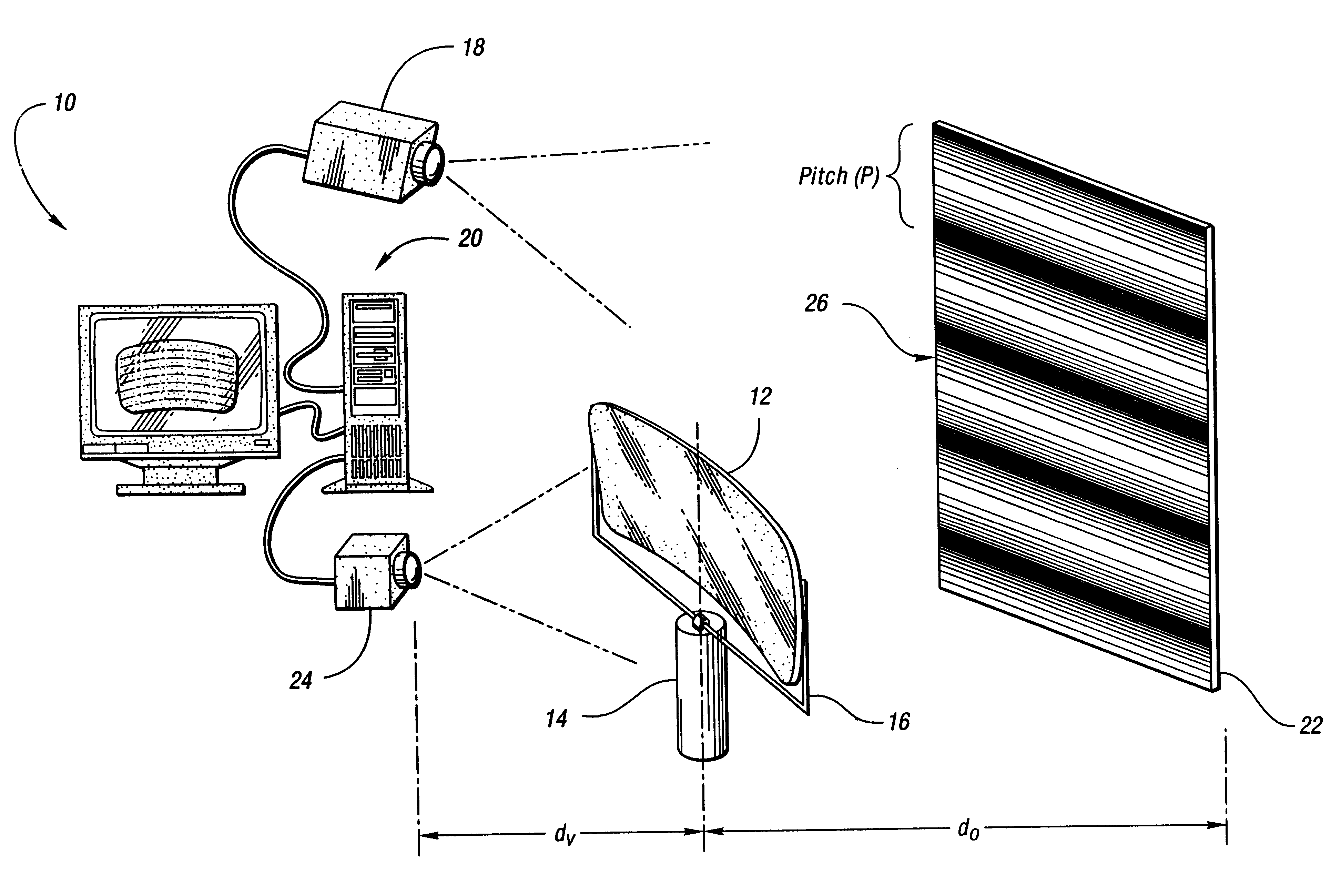
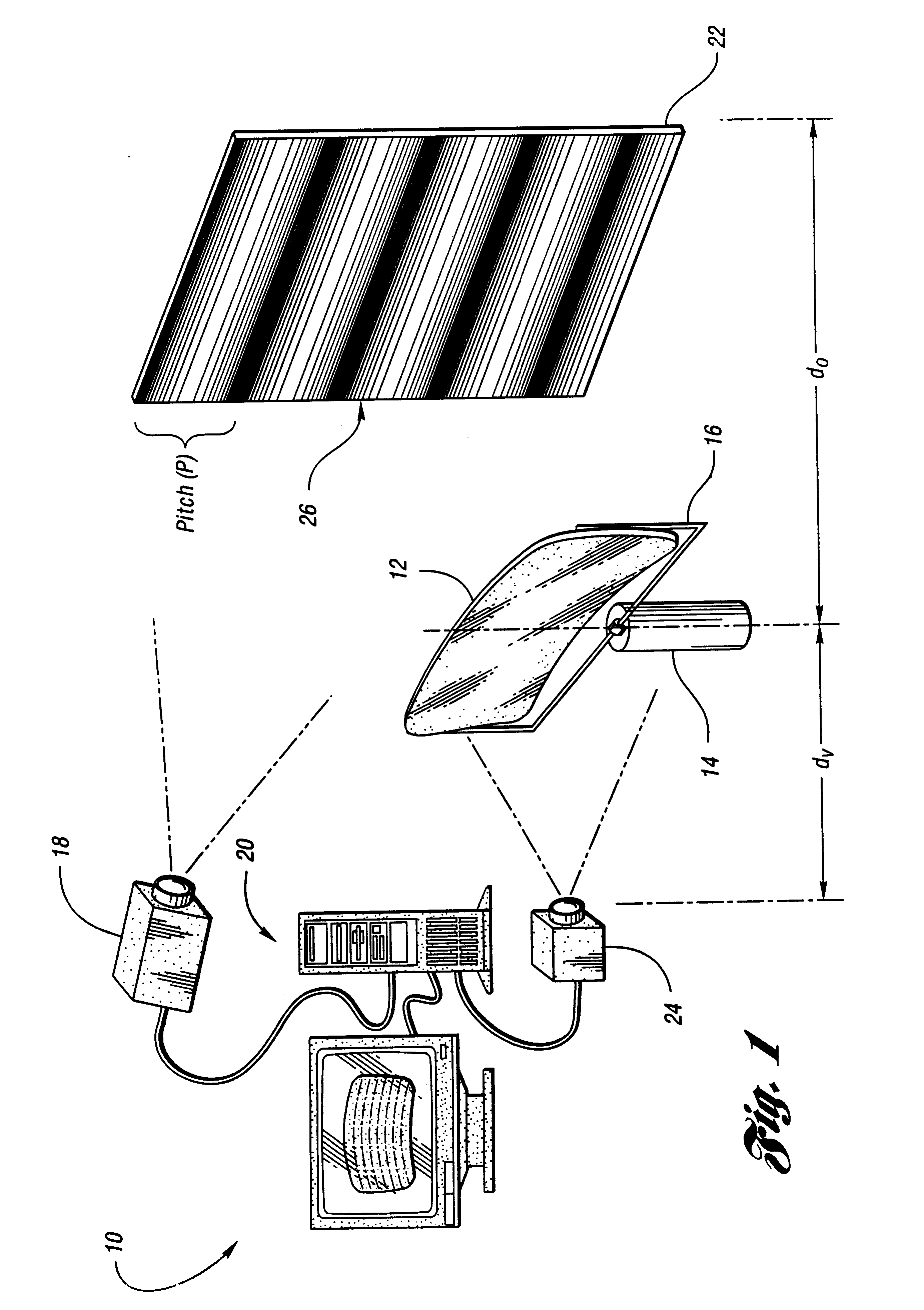
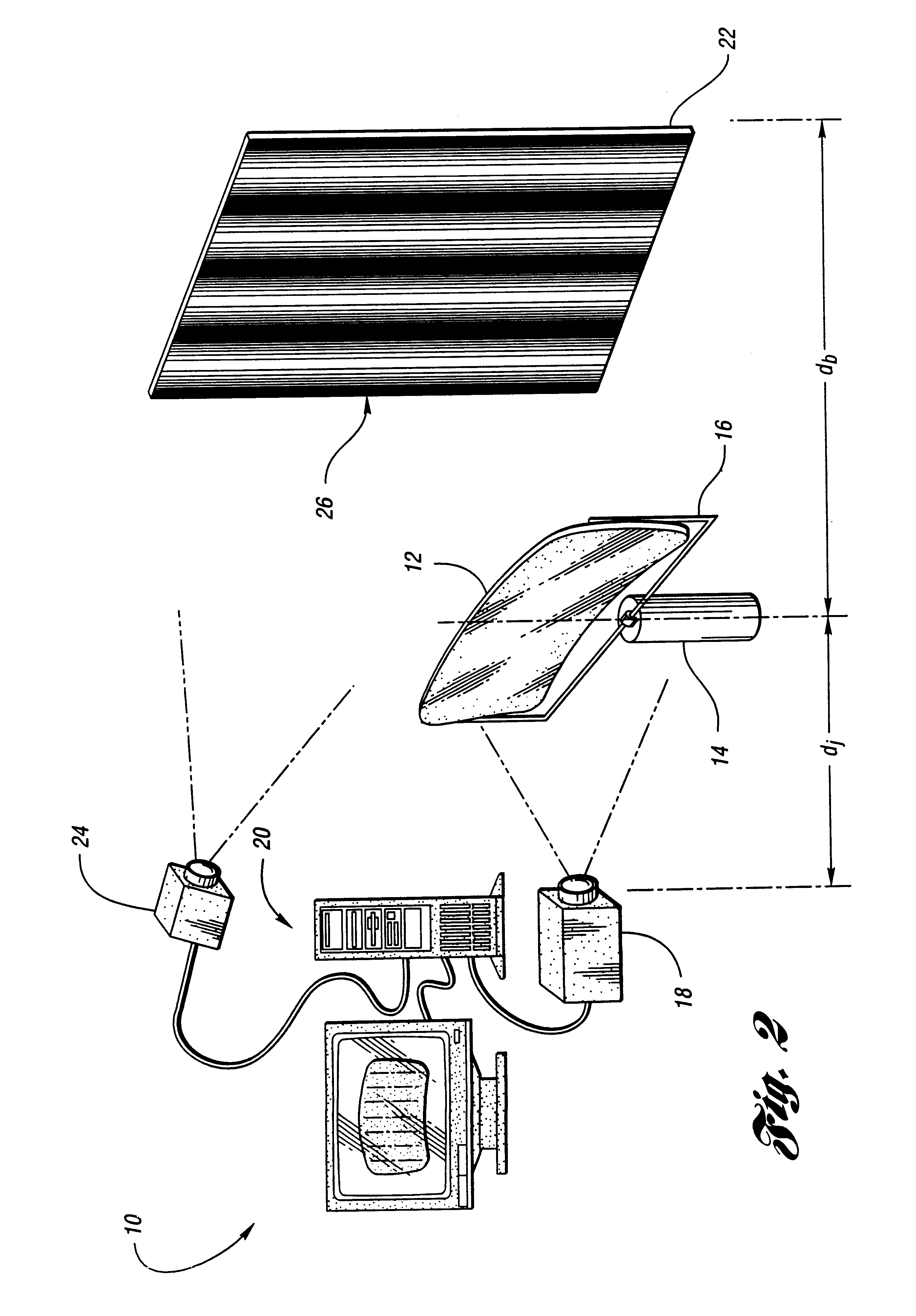
FIG. 1 shows an apparatus 10 according to the invention for determining optical quality of a transparent product such as a front windshield 12 for a motor vehicle. Other exemplary transparent products include magnifying glasses, eyeglasses, aircraft windshields, windows, and fluids having various indices of refraction. The windshield 12 is held in a predetermined position and angle of inclination on a rotatable work table 14 by means of a holder 16.

As shown in FIG. 1, the apparatus 10 includes a projector 18 in communication with a computer 20. The projector 18 is used to project one or more gray-scale targets or patterns onto a reference plane, such as a screen 22, which is located behind the windshield 12 at a distance d.sub.o from the windshield 12. Gray-scale pattern as used herein refers to a pattern having a varying light intensity or color profile, such as a sinusoidal grating or a sawtooth grating, wherein each point in the pattern has a well defined phase. Advantageously, t...


PUM


Abstract

A method of determining optical quality of a transparent product includes passing a first gray-scale pattern through the material; obtaining a first image of the first pattern with an image pickup device after the first pattern has passed through the material; and determining optical quality of the material based on data obtained from the first image. An apparatus for determining optical quality of such a material is also disclosed.

Description

The invention relates to an apparatus and method for determining optical quality of a transparent product, wherein the apparatus and method involve passing one or more gray-scale patterns through the product.A prior method for determining optical quality of a transparent product, such as a front windshield for a motor vehicle, involves projecting an array of dots through the product and onto a screen. The dots are then measured manually, and the measurements are compared with predetermined, standard measurements to evaluate optical distortion of the product.Because the dots are measured manually, this method is rather time-consuming, fatiguing and error prone. Furthermore, the method provides limited coverage of the product. For example, distortion occurring between dots is not detected.Another method for determining optical quality of a transparent product involves using a test pattern comprising a plurality of diamonds or equivalent pattern. A moveable light source is positioned b...

Claims


Application Information

Patent Timeline
IPC IPC(8): G01N21/956G01N21/88G01N21/958G01M11/00G01N21/23G01N21/49
CPCG01N21/958G01N2021/8832G01N2021/9586
Inventor LADEWSKI, THEODORE B.
Owner AUTOMOTIVE COMPONENTS HOLDINGS
Learn More