

Locking mechanism for portable valuables
a technology for valuables and locking mechanisms, applied in the field of locking mechanisms, can solve the problems of large opportunity for theft, small computer, and high-performance notebook computers with large screens, and achieve the effects of being resistant to tampering, simple structure, and inexpensive to manufacture and install
- Summary
- Abstract
- Description
- Claims
- Application Information
AI Technical Summary
Benefits of technology
Problems solved by technology
Method used
Image

Examples
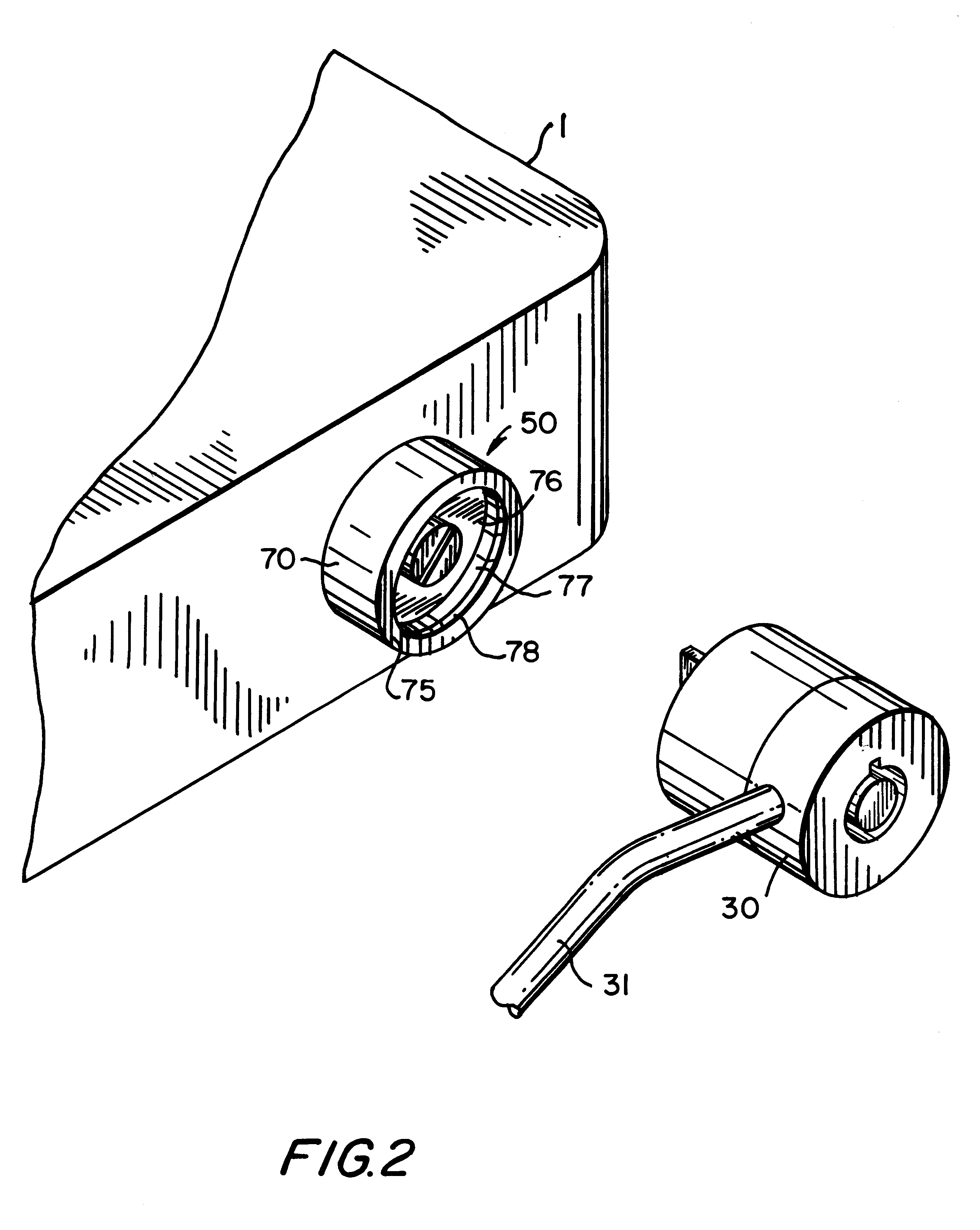
embodiment 50
The general theory of operation of locking mechanisms embodying the present invention, as well as a detailed description of the first preferred embodiment 50 of the present invention is shown in FIGS. 4-17.
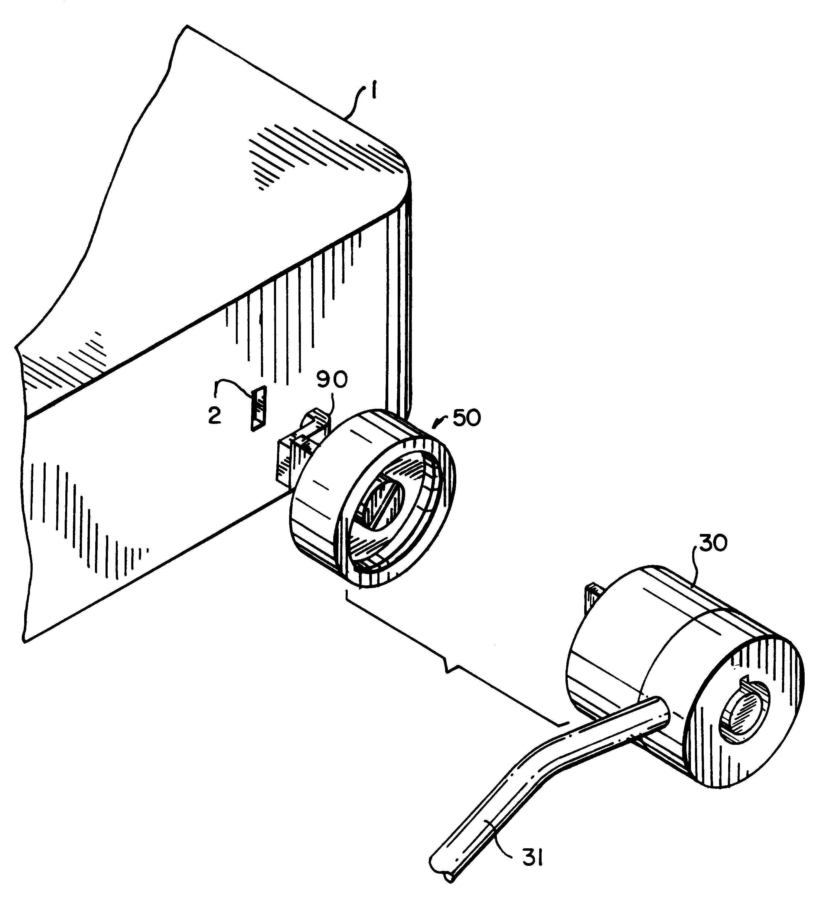
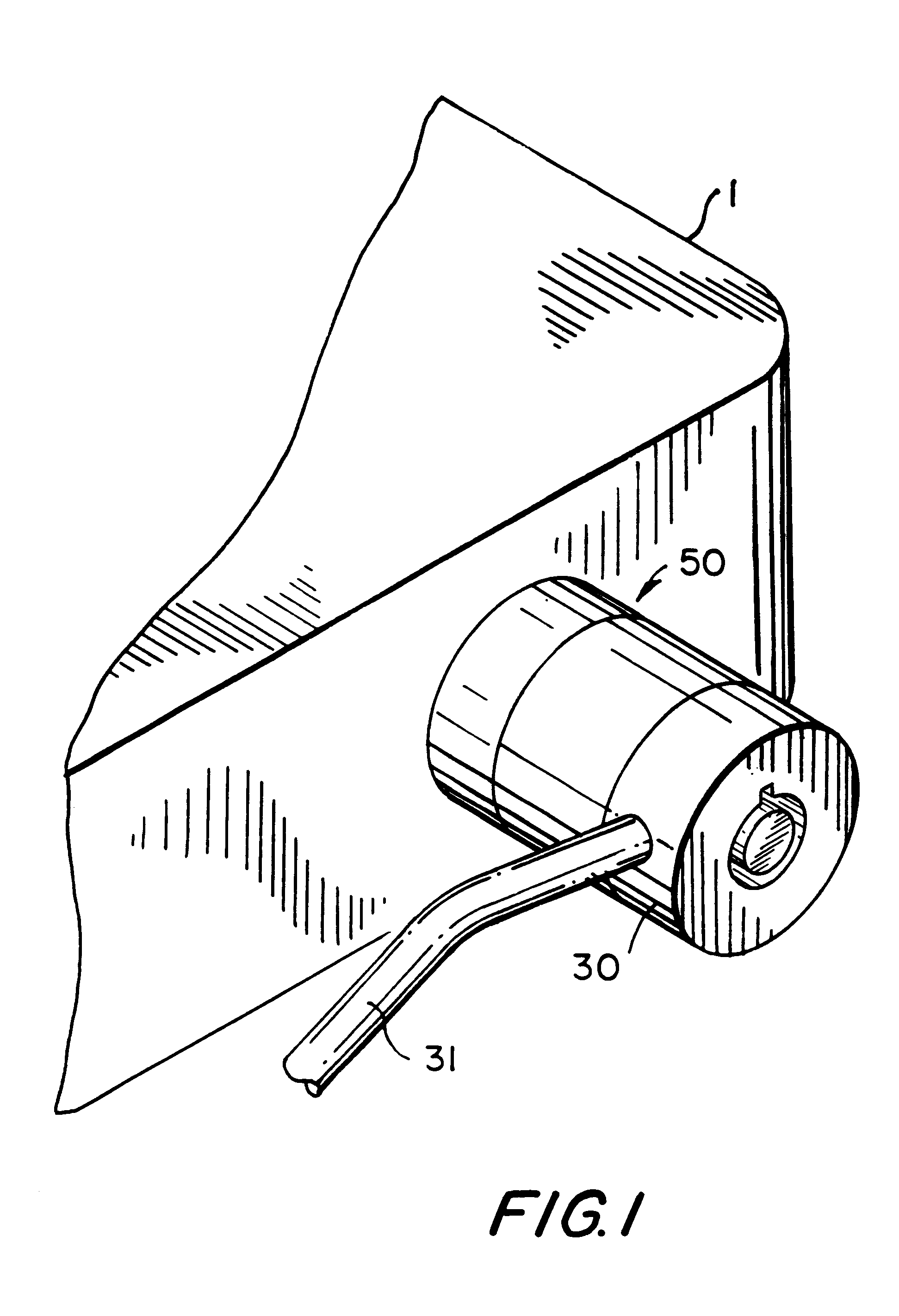
FIG. 4 illustrates the security slot 2 formed, by molding or otherwise as appropriate, in an exterior wall 3 of a portable valuable. The present "industry standard" security, or restraining slot has a generally rectangular configuration with long parallel sides 4 and short parallel sides 5, and rounded corners 6. The long dimension 7 of the slot is about seven millimeters and the short dimension 8 is about three millimeters. The corners 6 typically have a radius of curvature from about 0.3 millimeters to 1.5 millimeters. Surrounding the slot 2 is a circular space 10 concentric with the center of the slot and having a radius 11 approximately equal to half the long dimension 7 of the slot 2. Manufacturers of portable valuables incorporated with a security slot have reserved this cir...
first embodiment
In FIGS. 22-24, a third preferred embodiment of the locking mechanism, 50e, is constructed similarly to the locking mechanism 50 depicted and described above, with the exception that the recessed mounting cavity 72e of the housing 70e has an open side 79 that extends through the outer cylindrical wall 80e of the housing 70e. Also, fabricated on opposite walls 82e of the recessed cavity 72e are linear slots 81. The pins 106 of the restraining member 90 are mounted in slots 81. When mounted in slots 81, the restraining member 90 can be moved to an installation position where the shank 92 of the restraining member 90 extends outward and beyond the cylindrical wall 80e of the housing 70e, as depicted in FIG. 22.
FIGS. 25a-c illustrate the installation of the restraining member 90e of locking mechanism 50e into the security slot 2 of a portable valuable 1. As shown in FIG. 25a, the distal end 95e of the hook member 93e is aligned with the security slot 2; the shank 92e of the restraining ...
embodiment 430
The embodiment of FIGS. 49 and 50 may be slightly modified to provide an alternative embodiment 430 in which, in the lock receptacle 410a at surface 418a of circumferential edge 416a, a washer 420 is provided as shown in FIG. 51. Washer 420 may be pressed or glued to surface 418a and provides reinforcement to the edge 416a.
In FIGS. 52a and b, an alternative embodiment of the lock receptacle of the locking mechanism 400 according to the present invention is depicted wherein dimension 419a of edge 416a is sized such that the lock receptacle 410a will receive and securely engage a ball-type lock such as that described in U.S. Pat. No. 4,742,703, as well as others known in the art and commercially available. Preferably dimension 309a is about 1 to 1.5 millimeters.
FIGS. 53a and b illustrate another alternative embodiment of a lock receptacle of the present invention, 490, intended to securely engage a one-way latch clip-type lock, a variety of which are known in the art and are commercia...
PUM
 Abstract
Description
Claims
Application Information