Measuring receptacle having angled lines

a technology of receptacle and angled line, which is applied in the direction of measurement devices, instruments, and calibration of capacity, etc., can solve the problems of destroying the efficacy of a process, wasting time, and wasting resources, and achieves the effect of less time-consuming

Inactive Publication Date: 2001-04-10
MEASURITE CORP
View PDF3 Cites 14 Cited by
  • Summary
  • Abstract
  • Description
  • Claims
  • Application Information

AI Technical Summary

Benefits of technology

In the present invention, the markings in a set of level indicators can be shortened, and do not extend to the pouring mouth of the measuring jug when the operator is using that set of markings to dispense or retain a certain volume of fluid. The markings need only to extend over a small section of the jug, not the entire surface of the jug. This has obvious advantages for manufacturers and users of the measuring jug.
For manufacturers, it will be easier, less time consuming and cheaper to not have to extend two separate scales of lines over a jug surface, as is the case with New Zealand Patent No. 211520. The markings comprising a set of fluid level indicators form a small unit / symbol on the jug surface with the markings comprising line segments rather than long lines in the preferred embodiment. In fact, the line segments may be as small as will permit alignment with a surface level of fluid, depending on the user's requirements for accuracy.
The markings not extending to the pouring mouth will have obvious benefits for consumers. It is easier for consumers to appreciate that the two lines in a set of level indicators (in the preferred embodiment of the jug ie. the pouring line and filling line) are correlated. The system of operation, and underlying concept will be more apparent to the operator.

Problems solved by technology

This can have serious consequences, such as destroying the efficacy of a process.
The problems of overfilling and repouring can also prove expensive if costly materials are used, or the pouring process has to be recommenced.
The time-consuming nature of having to make a series of small pours is also a problem.
In addition, even if a user judges that the fluid has reached the right level and that the surface of the fluid is aligned with the line segment indicating a certain volume, the short length of the line segment and / or the jug not being held precisely upright results in known measuring receptacles proving inaccurate measuring devices, unable to dispense or hold accurate measures of liquid.
As the fluid approaches the desired level, the process is much more deliberate, careful and time consuming.
A major problem with known receptacles such as beakers and cylinders as discussed above is therefore that the receptacle must always be returned from a tilted position when the fluid is being poured to an upright position, so that the fluid surface can be aligned with horizontal markings on the vessel, and the fluid level in the receptacle thus ascertained.
This process is time consuming and inaccurate, and often results in more than the desired quantity of fluid being dispensed from the receptacle, or insufficient fluid retained in the receptacle when the operator is in a hurry.
This may have disastrous consequences for either the domestic or industrial user.
This system significantly reduces the time taken to dispense liquid.
Although an improvement over known measuring devices, it is now acknowledged that use of the measuring jug in New Zealand Patent No. 211520 still has certain difficulties.
A user may not appreciate the purpose of the pour lines, and may simply ignore them.
A further problem with the jug in New Zealand Patent No. 211520 is that respective pouring lines and filling lines are accorded their own numerical values.
Being so apparently complicated in appearance, manufacturers are reluctant to make the high investment in tooling costs because of doubt about public acceptance of the jug in the market place.
Another disadvantage of the jug of New Zealand Patent No. 211520 is that the two scales--the pouring lines and the filling lines--radiate over the entire surface of the jug.
The extension of lines and numbers over the jug surface provides difficulties to manufacturers of the jugs--the lines and numerals must be efficiently applied so that manufacture is viable.
This process is time consuming, and may require extensive modifications to existing methods of marking jugs, or even the development of new technology.
In particular, there is considerable visual confusion at the pouring mouth of the jug where the lines all converge.

Method used


Image

  • Measuring receptacle having angled lines
  • Measuring receptacle having angled lines
  • Measuring receptacle having angled lines

Examples


Embodiment Construction

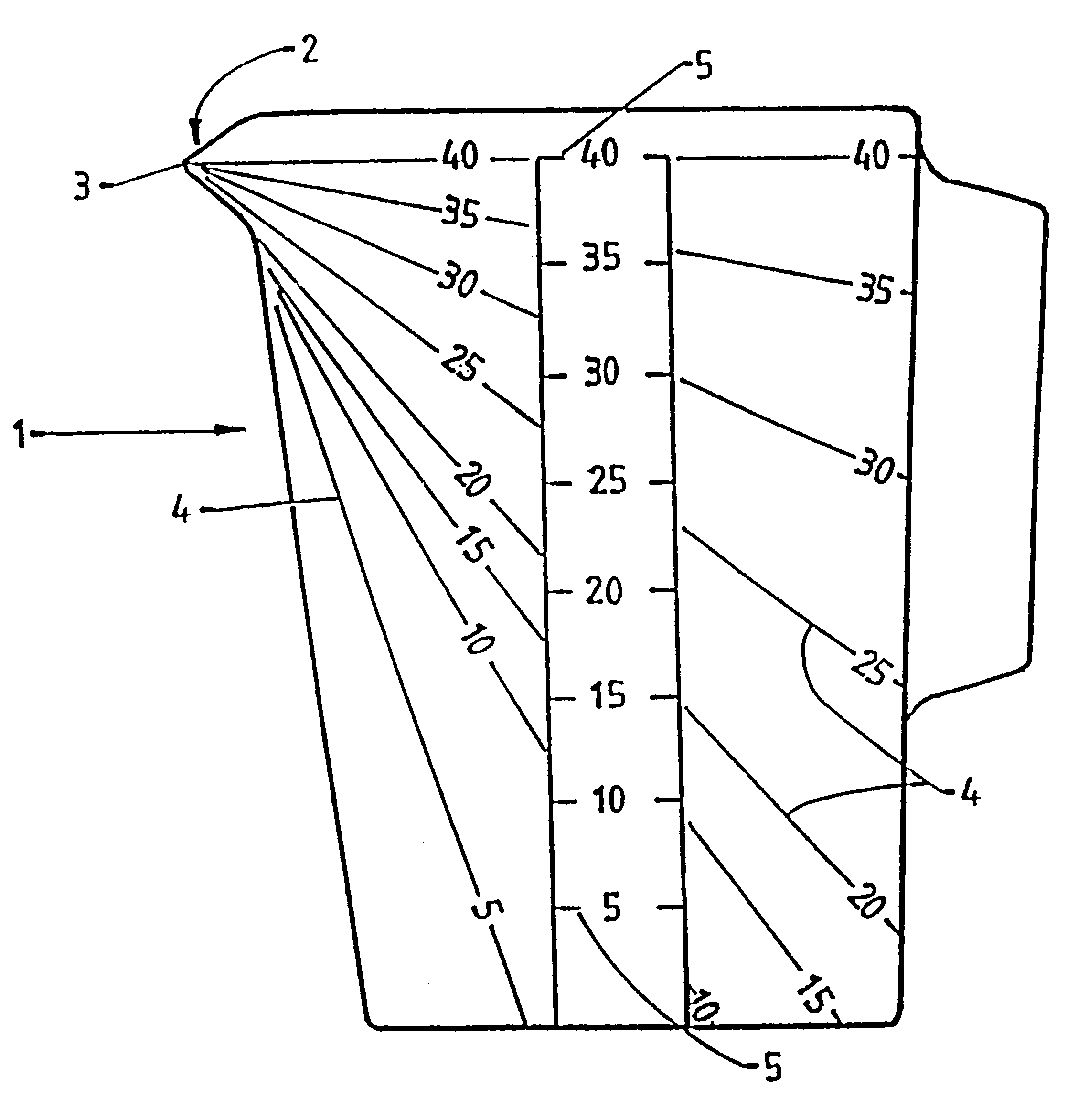
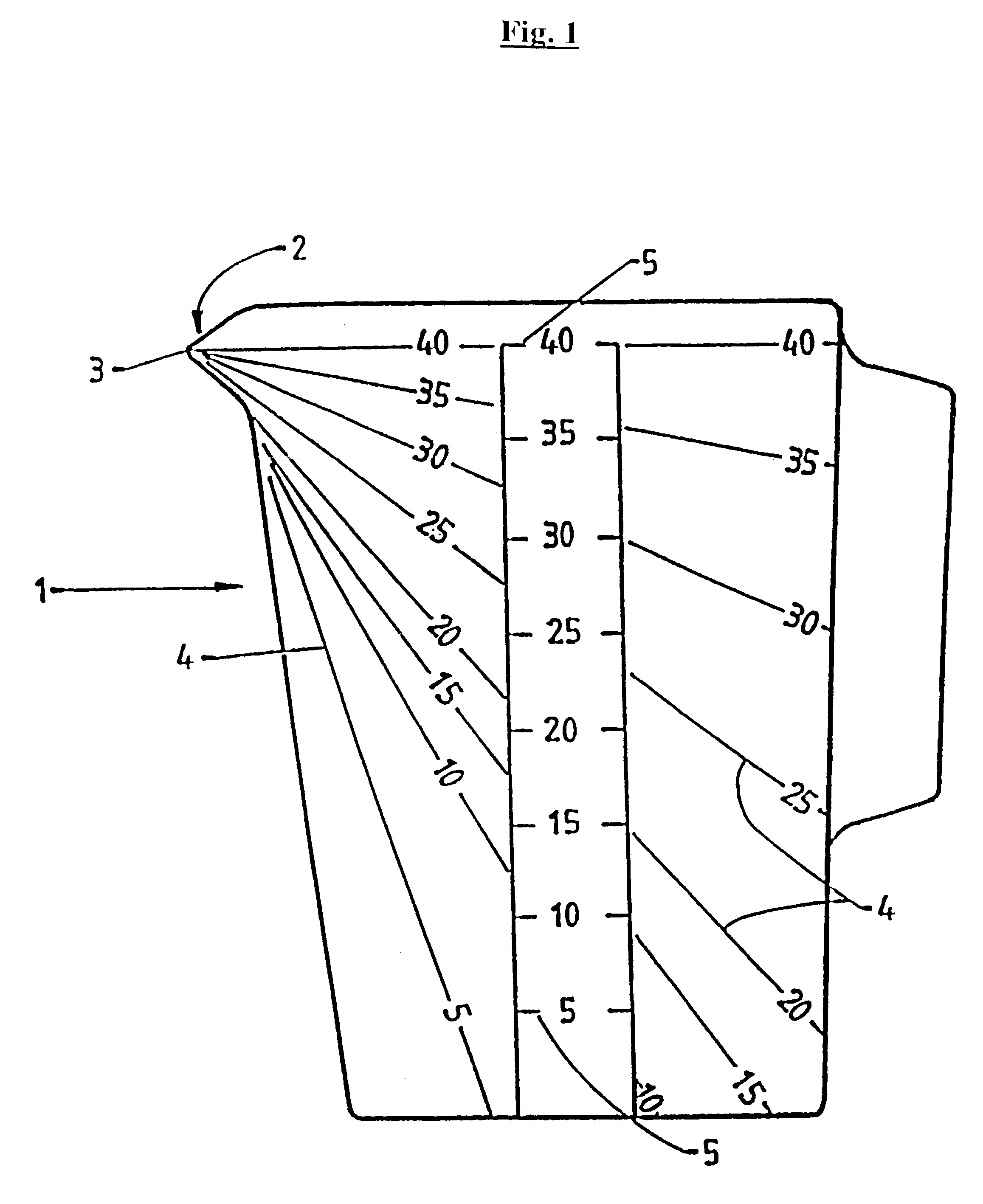
The jug illustrated in FIG. 1 shows the closest prior art and is included to highlight the advantages of the present invention thereover.

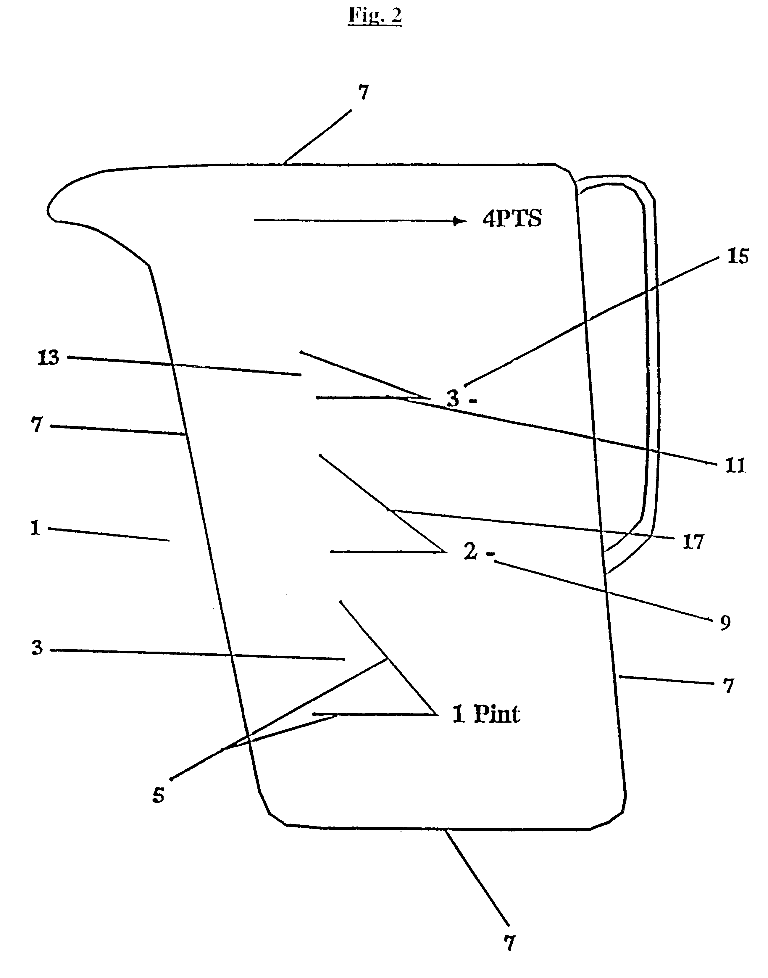
Referring to FIG. 2, the receptacle holding fluid is represented by a measuring jug 1. A set of fluid level indicators 3 consists of the two markings, being the lines 5. The lines 5 do not extend to the visual perimeters 7 of the measuring jug 1.

In this embodiment, the three sets of fluid level indicators also have a volume indicator eg a volume of two pints is represented by 9 placed at the convergence of the lines 5.

It can be clearly seen that the indicators on the jug in FIG. 2 are less cluttered and gives greater visual acuity than the jug in FIG. 1.

In use, an operator will fill the measuring jug 1 with liquid to a certain level. For example, if it is wished to dispense a pint of liquid a user may fill the jug 1 until the surface of the fluid corresponds with the level represented by the horizontal filling line 11 in the set of markings 13 havi...


PUM


Abstract

This invention relates to a receptacle (1) capable of holding fluid and having one or more sets of fluid level indicators, wherein a set of fluid level indicators (3) comprises at least two markings (5), characterized in that when the level indicators are viewed during use of the receptacle, the markings do not extend to the pouring mouth of the receptacle (7).

Description

This invention relates to a receptacle. In particular, this invention relates to receptacles capable of holding fluid.Receptacles capable of holding fluid, such as measuring jugs, beakers and measuring cylinders, are well known. Such receptacles have wide ranging domestic and commercial applications. Consumers are familiar with their domestic, especially culinary, application.Such receptacles are also commonly used in technical fields, notably in dispensaries and laboratories, and a wide range of receptacles are commonly used to dispense and hold particular quantities of fluid materials. Customarily, receptacles such as measuring jugs bear series graduations with differing volumes indicated by horizontal lines circling or marked across the side of the container. The user holds the receptacle in an upright position to fill it with an appropriate quantity of fluid, and dispenses the fluid by constantly tipping the receptacle and returning it to an upright position, until the fluid is ...

Claims


Application Information

Patent Timeline
Patent Type & Authority Patents(United States)
IPC IPC(8): G01F19/00A47J47/00
CPCG01F19/00
Inventor BETHUNE, DONALD RAYMOND PETER
Owner MEASURITE CORP
Why Eureka
Try Eureka