Metal bus bar and tab application method

a technology applied in the field of metal bus bar and tab application method, can solve the problems of film darkening and term retention

Inactive Publication Date: 2001-04-10
PPG IND OHIO INC
View PDF10 Cites 149 Cited by
  • Summary
  • Abstract
  • Description
  • Claims
  • Application Information

AI Technical Summary

Problems solved by technology

In addition, these devices exhibit long-term retention of a chosen optical state, requiring no power consumption to maintain that optical state.
When the electrode adjacent to the electrochromic film is the cathode, application of an electric field causes darkening of the film.

Method used


Image

  • Metal bus bar and tab application method
  • Metal bus bar and tab application method
  • Metal bus bar and tab application method

Examples


example 1

Tab Application

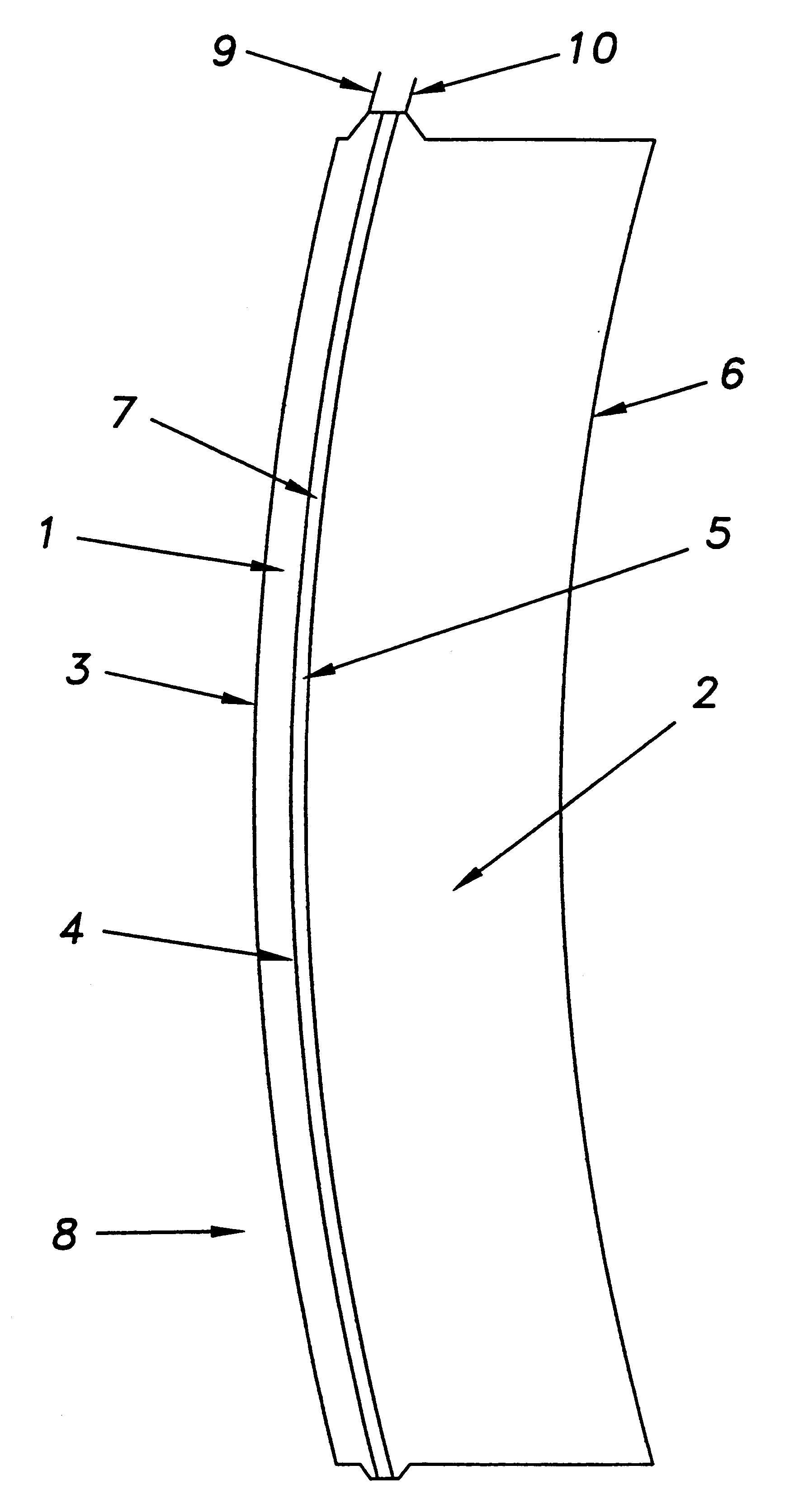
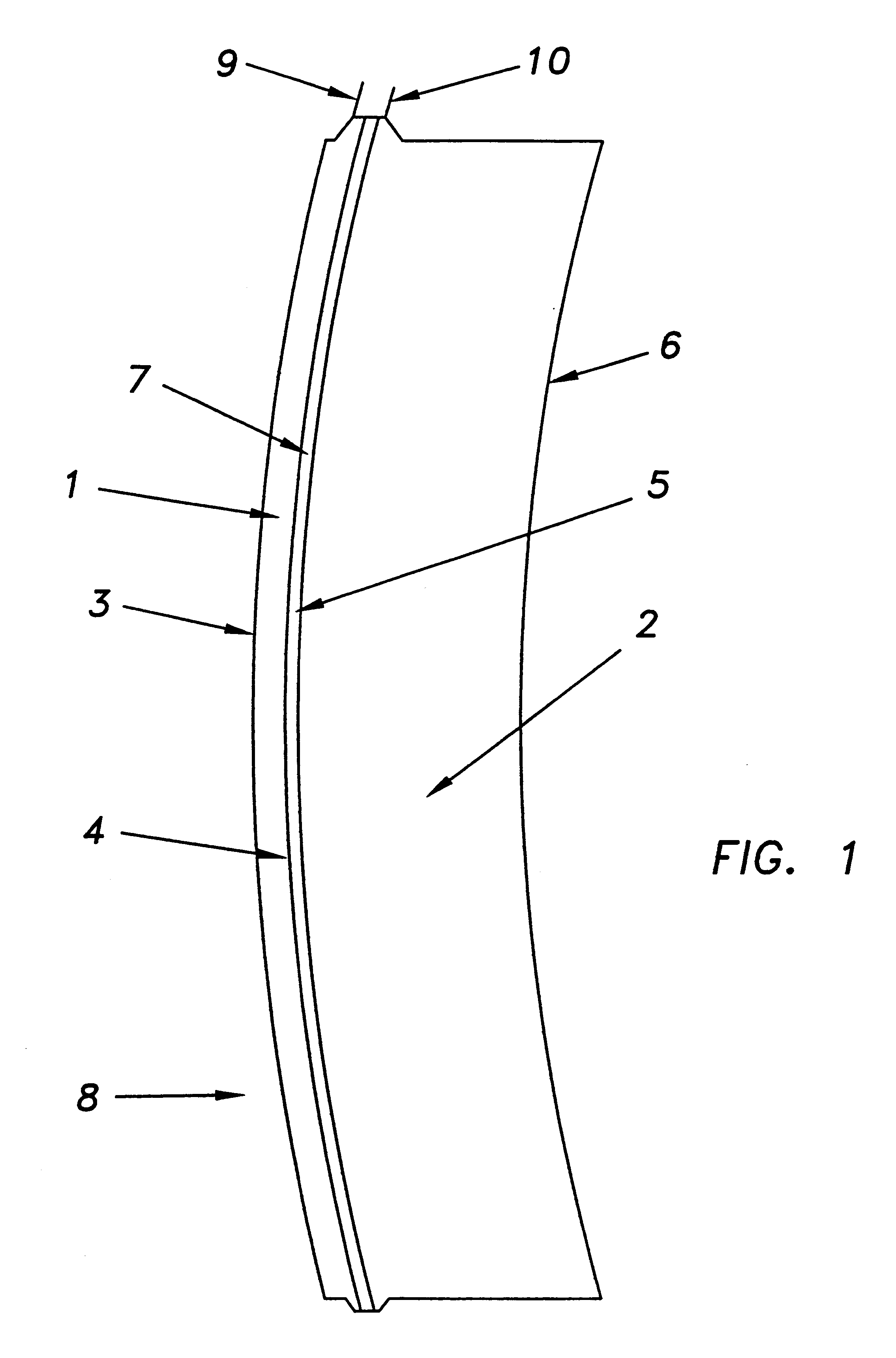
The peripheral edge regions of two (2) shaped 1-2 mm thick clear optical lenses prepared from CR-39.RTM. monomer were coated with chromium and gold, 1000 and 6000 .ANG. thick, respectively, using conventional sputter deposition techniques. The resulting gold / chromium bus bars covered the full peripheral edge regions of each lens.

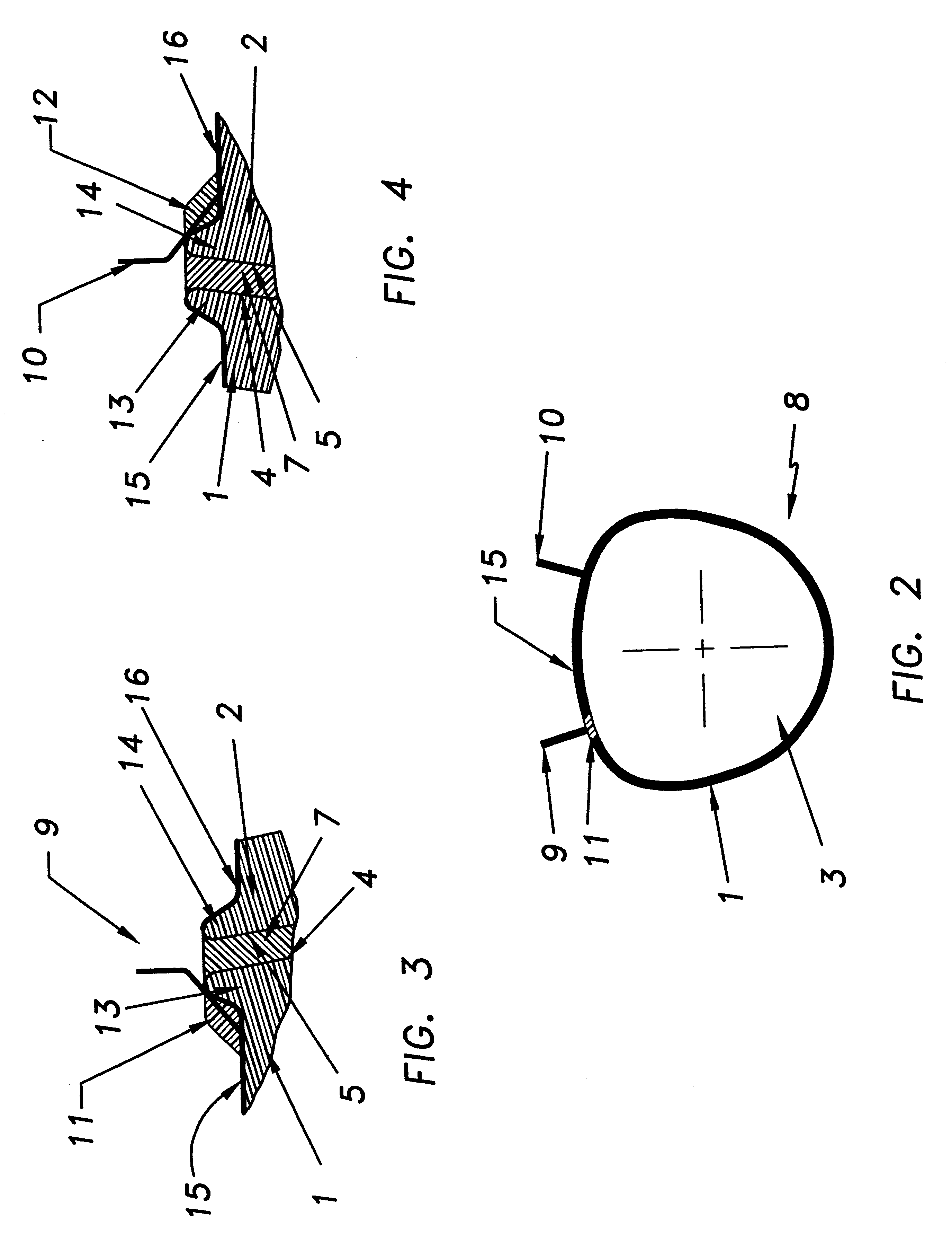
Two (2) commercially available gold-plated nickel tabs 0.0005 in (0.013 mm) thick by 0.04 inch (1.0 mm) wide were cleaned and dried via conventional techniques and cut to 0.25 inch (6.4 mm) lengths. These tabs were then attached to the bus bars of the above-described lenses by the following techniques:

A. Structural Epoxy

1. One of the lenses was placed on a tab location template and marked accordingly. With the aid of a microscope, a small amount of Araldite 2012 structural epoxy was applied to the marked tab location on its chromium / gold bus bar.

2. The connecting end of the tab was placed onto the Araldite 2012, and the epoxy was cured, in acc...


PUM

PropertyMeasurementUnit
thickaaaaaaaaaa
thickaaaaaaaaaa
cure temperaturesaaaaaaaaaa

Abstract

A method for applying a conductive metal bus bar/tab system to the peripheral edge region of a substrate, such as an ophthalmic lens, is disclosed. The method involves: 1) applying conductive metal bus bar to said substrate; and 2) attaching a tab to said bus bar so as to ensure electrical contact between the tab and bus bar. Related devices are also disclosed.

Description

This invention relates to a method for applying an electrical contact system to a substrate, and to the resulting metallized substrate. A preferred embodiment involves applying a tab to a conductive metal bus bar on an optical substrate, such as an ophthalmic lens, using a bonding agent and, if necessary, a conductive intermediate. The instant method is particularly useful in preparing electrooptic devices, such as electrochromic lenses.BACKGROUND OF THE ARTThe transmittance properties of electrochromic materials change in response to electrically driven changes in oxidation state. Thus, when an applied voltage from an external power supply causes electrons to flow to (reduction) or from (oxidation) an electrochromic material, its transmittance properties change. In order to maintain charge neutrality, a charge balancing flow of ions in the electrochromic device is needed. By enabling the required electron and ion flows to occur, an electrochromic device facilitates reversible oxida...

Claims


Application Information

Patent Timeline
Patent Type & Authority Patents(United States)
IPC IPC(8): B32B17/06B32B17/10G02F1/01G02F1/153H05B3/84G02F1/155
CPCB32B17/10486G02F1/153H05B3/84H05B2203/016G02F1/155
Inventor SMARTO, JOHN E.
Owner PPG IND OHIO INC
Why Eureka
Try Eureka