
Control for watercraft engine

a technology for watercraft engines and control systems, applied in the direction of marine propulsion, vessel construction, propulsive elements, etc., can solve the problems of sensor determining whether the low pressure is indicative of an actual or not, and the difficulty of accurately sensing the level of lubricant remaining in the lubricant pan becomes difficult, if not impossible, and the engine designer is faced with unique challenges

Inactive Publication Date: 2001-04-10
SANSHIN KOGYO CO LTD
View PDF7 Cites 41 Cited by
  • Summary
  • Abstract
  • Description
  • Claims
  • Application Information

AI Technical Summary

Benefits of technology

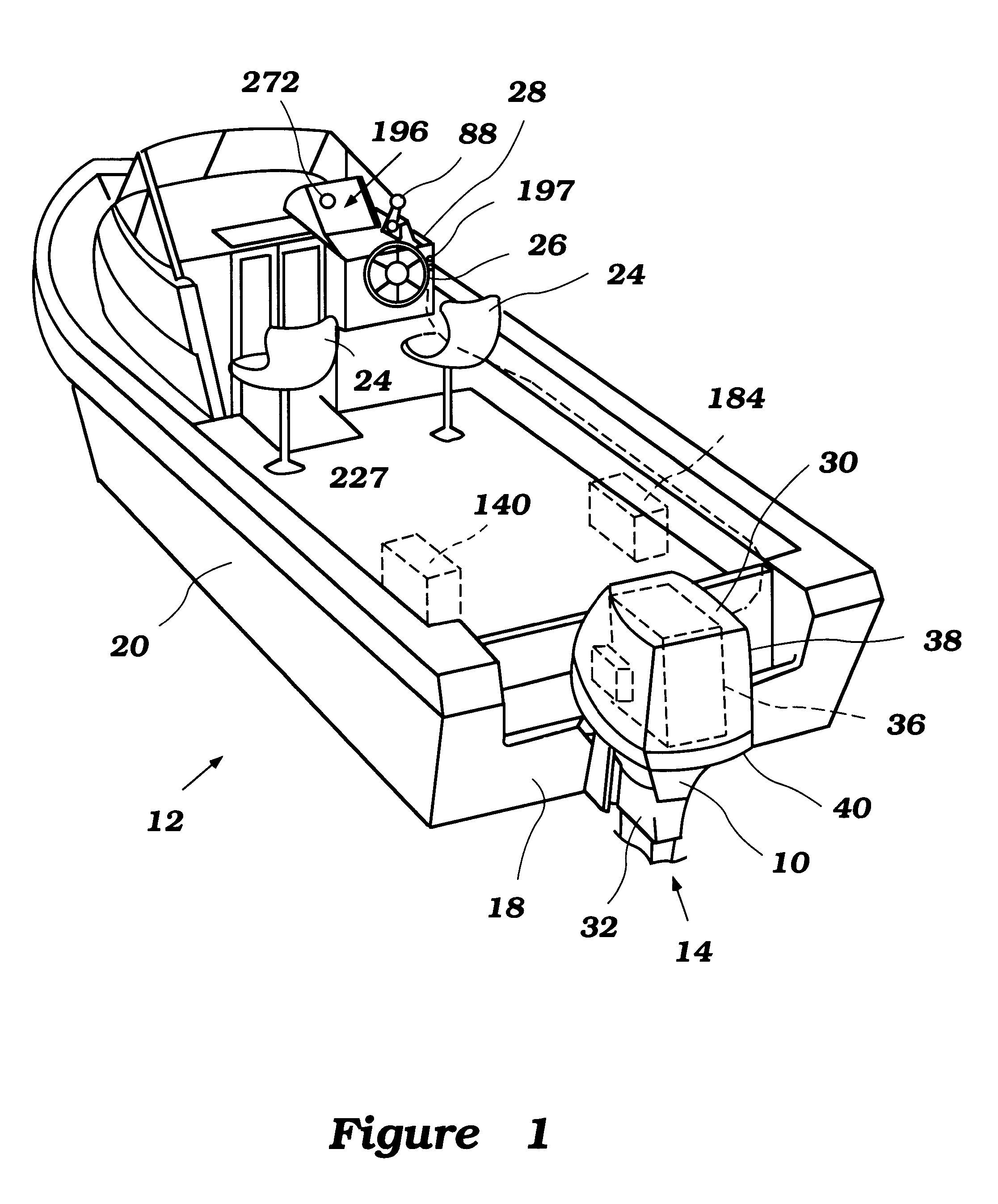
With initial reference to FIG. 1, an outboard motor 10 for powering a watercraft 12 is illustrated. The outboard motor 10 advantageously has a lubrication alarm system arranged and configured in accordance with certain features, aspects, and advantages of the present invention. The outboard motor 10 provides an exemplary environment in which the control system has particular utility. The lubrication alarm system of the present invention may also find utility in applications having engines that experience rapid fluctuations in lubrication system pressures and reservoirs that may experience significant sloshing or reorientation, such as, for example but without limitation, personal watercraft, small jet boats, offroad vehicles, circle track racing vehicles, and heavy construction equipment.

Problems solved by technology

Outboard motors pose unique challenges to engine designers due to their orientation and the rotation of the engines about a tilting and trimming axis during operation.
One such challenge involves supplying lubricant to the moving components of the engine during a variety of operating conditions.
Because the orientation of the engine changes during use, accurately sensing a level of lubricant remaining in an lubricant pan becomes difficult, if not impossible.
One difficulty in such sensors is determining whether the low pressure is indicative of an actual problem or, rather, is indicative of a sudden change in operating conditions.
For example, although an outboard motor may generate sufficient minimum oil pressure at idle so as to prevent a conventional oil pressure alarm system from being triggered, the engine may operate at higher speeds with an inadequate flow rate of oil.
Although the engine may generate sufficient oil pressure at idle, a leak or a blockage within the engine may cause the oil pressure to fall below the appropriate pressure for the corresponding engine speed above idle.
Thus, conventional systems do not adequately address the problems associated with lubricant pressure irregularities at engine speeds above idle.
For example, if a vehicle is operated in a rough manner, liquid lubricant in an lubricant pan of the engine may be violently sloshed within the lubricant pan.

Method used


Image

  • Control for watercraft engine
  • Control for watercraft engine
  • Control for watercraft engine

Examples


Embodiment Construction

With initial reference to FIG. 1, an outboard motor 10 for powering a watercraft 12 is illustrated. The outboard motor 10 advantageously has a lubrication alarm system arranged and configured in accordance with certain features, aspects, and advantages of the present invention. The outboard motor 10 provides an exemplary environment in which the control system has particular utility. The lubrication alarm system of the present invention may also find utility in applications having engines that experience rapid fluctuations in lubrication system pressures and reservoirs that may experience significant sloshing or reorientation, such as, for example but without limitation, personal watercraft, small jet boats, offroad vehicles, circle track racing vehicles, and heavy construction equipment.

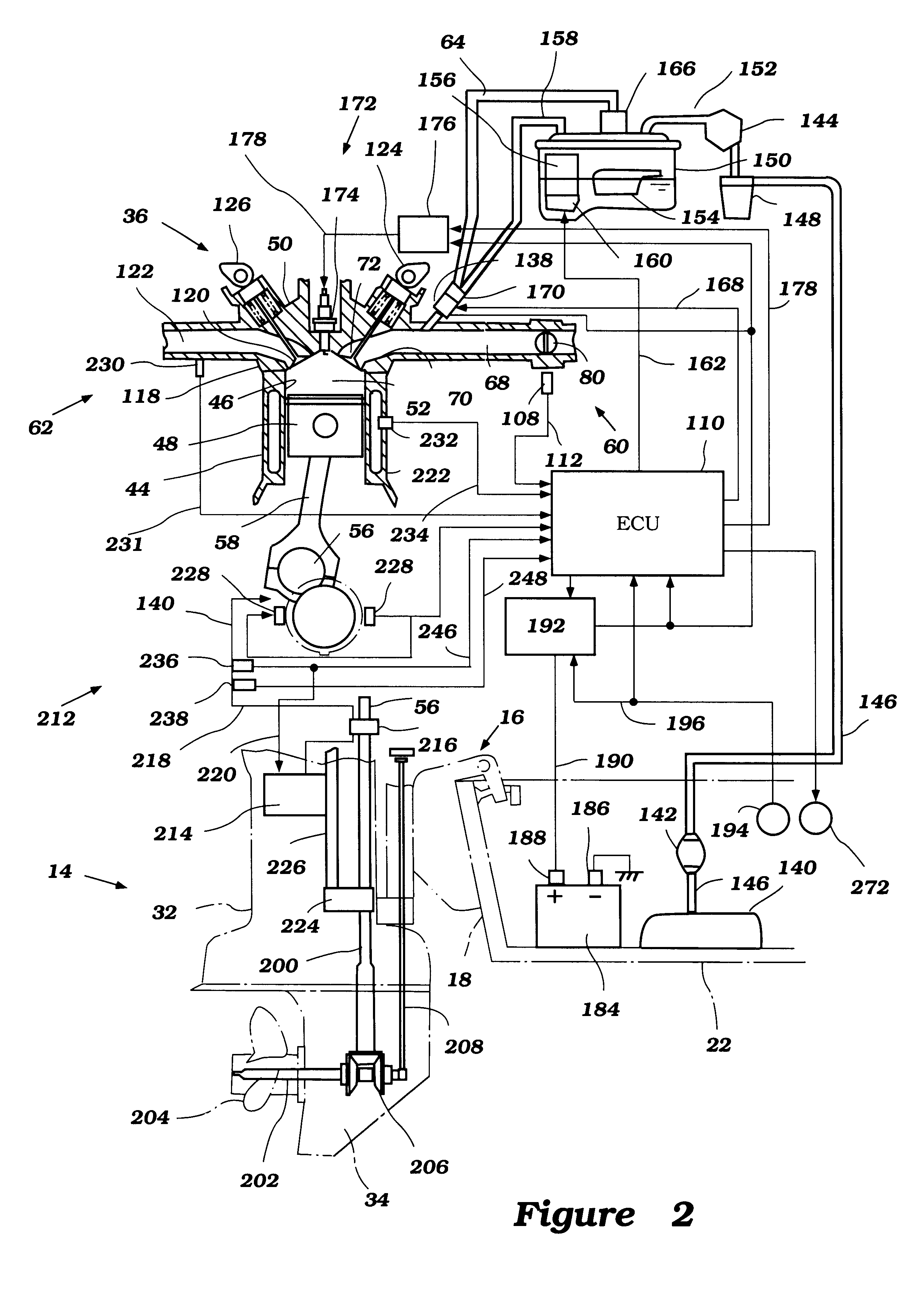
With reference to FIG. 2, in the illustrated embodiment, the outboard motor 10 comprises a drive unit 14 and a bracket assembly 16. Although schematically shown in FIGS. 1 and 2, the bracket assembl...


PUM


Abstract

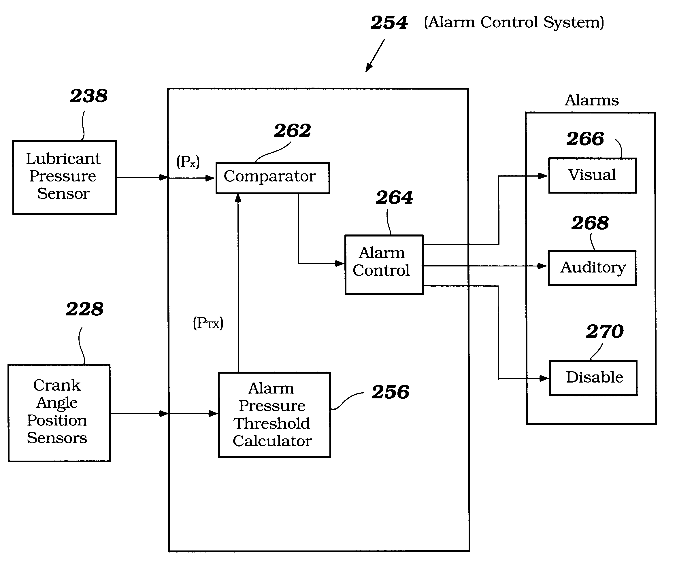
A watercraft engine includes a lubrication system alarm control system which initiates an alarm when lubricant pressure within the lubrication system falls below an acceptable pressure. The alarm system compares lubricant pressure during engine operation with a lower pressure threshold which is determined as a function of engine speed. Thus, partial reductions in lubricant pressure are identified. Additionally, the alarm control system may be configured to emit an alarm if lubricant pressure fluctuates at a rate that is greater than a predetermined pressure fluctuation rate threshold.

Description

PRIORITY INFORMATIONThis application is based on and claims priority to Japanese Patent Application No. 11-44465 filed Feb. 23, 1999, the entire contents of which is hereby expressly corporated by reference.1. Field of the InventionThe present invention generally relates to alarm control systems for engines. More specifically, the present invention relates to alarm control systems for lubrication systems of engines of outboard motors.2. Description of Related ArtOutboard motors pose unique challenges to engine designers due to their orientation and the rotation of the engines about a tilting and trimming axis during operation. One such challenge involves supplying lubricant to the moving components of the engine during a variety of operating conditions. Because the orientation of the engine changes during use, accurately sensing a level of lubricant remaining in an lubricant pan becomes difficult, if not impossible. Accurate monitoring of the lubricant is desirable to ensure that th...

Claims


Application Information

Patent Timeline
IPC IPC(8): F02B61/00F02B61/04F01M1/20
CPCF02B61/045
Inventor KANNO, ISAO
Owner SANSHIN KOGYO CO LTD
Learn More