Fastener assembly

a technology of fasteners and components, applied in the field of fasteners, can solve the problems of affecting the service life of the fastener, and affecting the service life of the fastener, and achieve the effect of simple disassembly in the device and easy disassembly

Inactive Publication Date: 2001-04-24
TOSKA
View PDF15 Cites 32 Cited by
  • Summary
  • Abstract
  • Description
  • Claims
  • Application Information

AI Technical Summary

Benefits of technology

An attaching device can be simply charged with the aforementioned fastener assembly in a set and in an array and can be simply disassembled in the device into individual fasteners so that each of these fasteners is enabled to attach a price tag or label to a commodity with a loop of its filament portio...

Problems solved by technology

However, this retaining member causes a problem that the commodity is holed because of piercing the hollow needle into the commodity to bring the cross bar portion to the back side of the commodity.
Moreover, the application is restricted to such a thin commodity or clothes as can pass the hollow needle easily.
Since the price tag is held by hooking the cross bar and the head portion in the hole, moreover, this hole is widened to damage the commodity if the price tag is pulled.
Still moreover, regarding the retaining member, there is a limit that the retaining member can not be manually attached and the attaching device can not be dispensed with.
Because of the type in which the retention is made by the cross bar portion and the head portion, moreover, the retaining member is liable to pass through...

Method used


Image

  • Fastener assembly
  • Fastener assembly
  • Fastener assembly

Examples


first embodiment

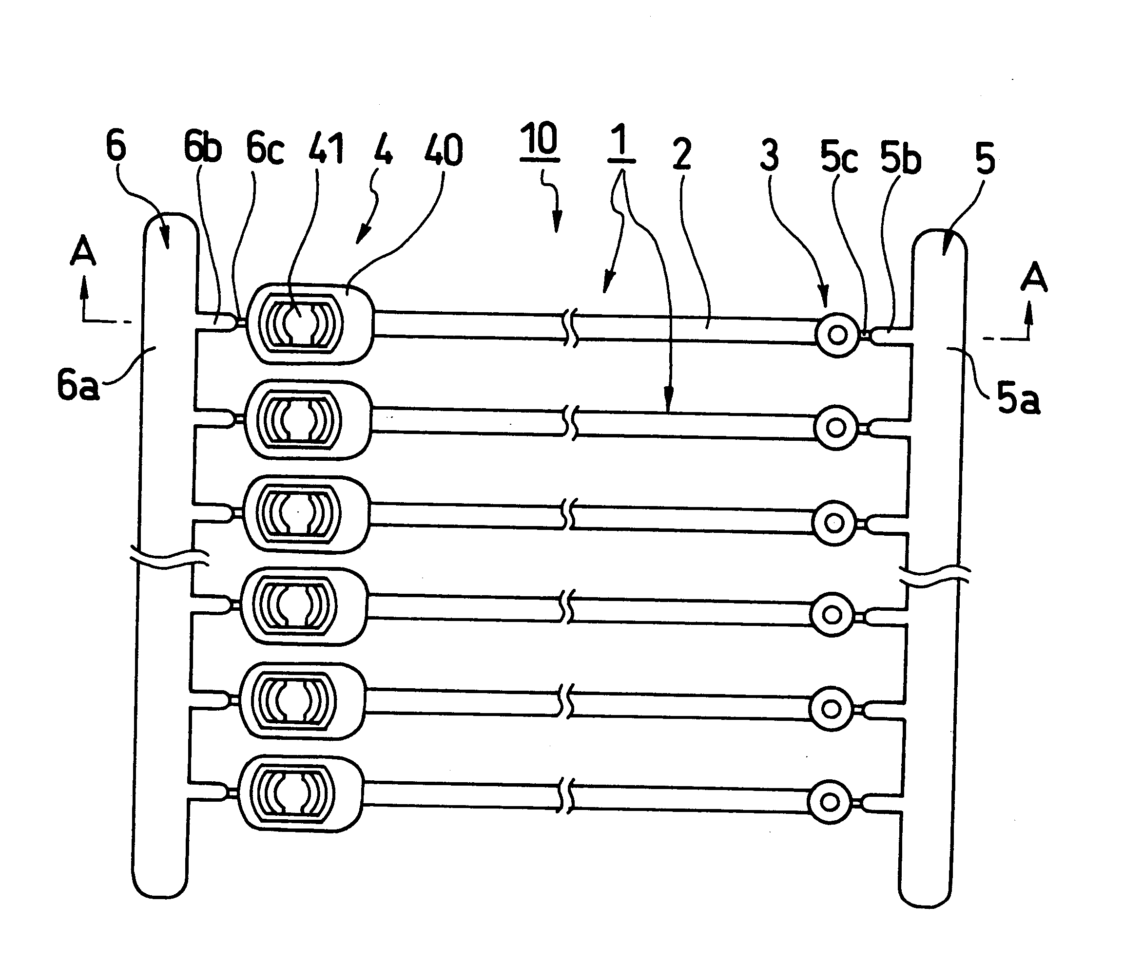
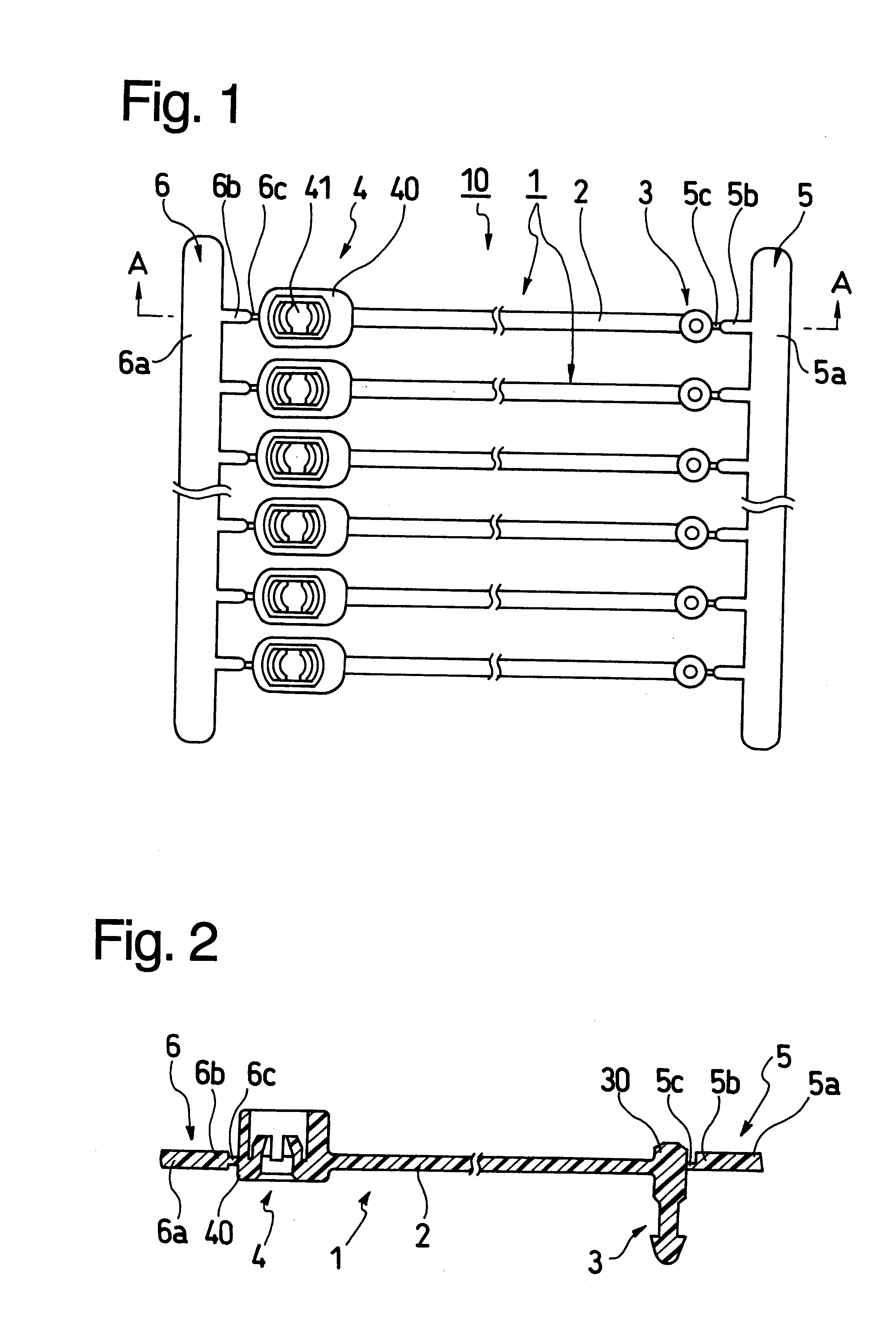
First of all, the fastener assembly 10 of a first embodiment, as shown in FIGS. 1 and 2, corresponds to the construction in which the filament portions 2 have a relatively large length or a relatively low rigidity. The first joint member 5 is formed of: a first joint rod 5a having a relatively large sectional area and a relatively high strength; first projections 5b projecting in the shape of comb teeth from the first joint rod 5a; and first cutting portions 5c leading from the first projections 5b to the trunk portions 30 of the retaining projections 3 and formed in the extending direction of the filament portions 2 while being reduced in their sections to be easily cut. The first joint member 5 thus formed is jointed to the retaining projections 3 on the side opposed to the filament portions 2.

Like the first joint member 5, on the other hand, the second joint member 6 is formed of: a second joint rod 6a having a relatively high rigidity; second projections 6b projecting in the sha...

second embodiment

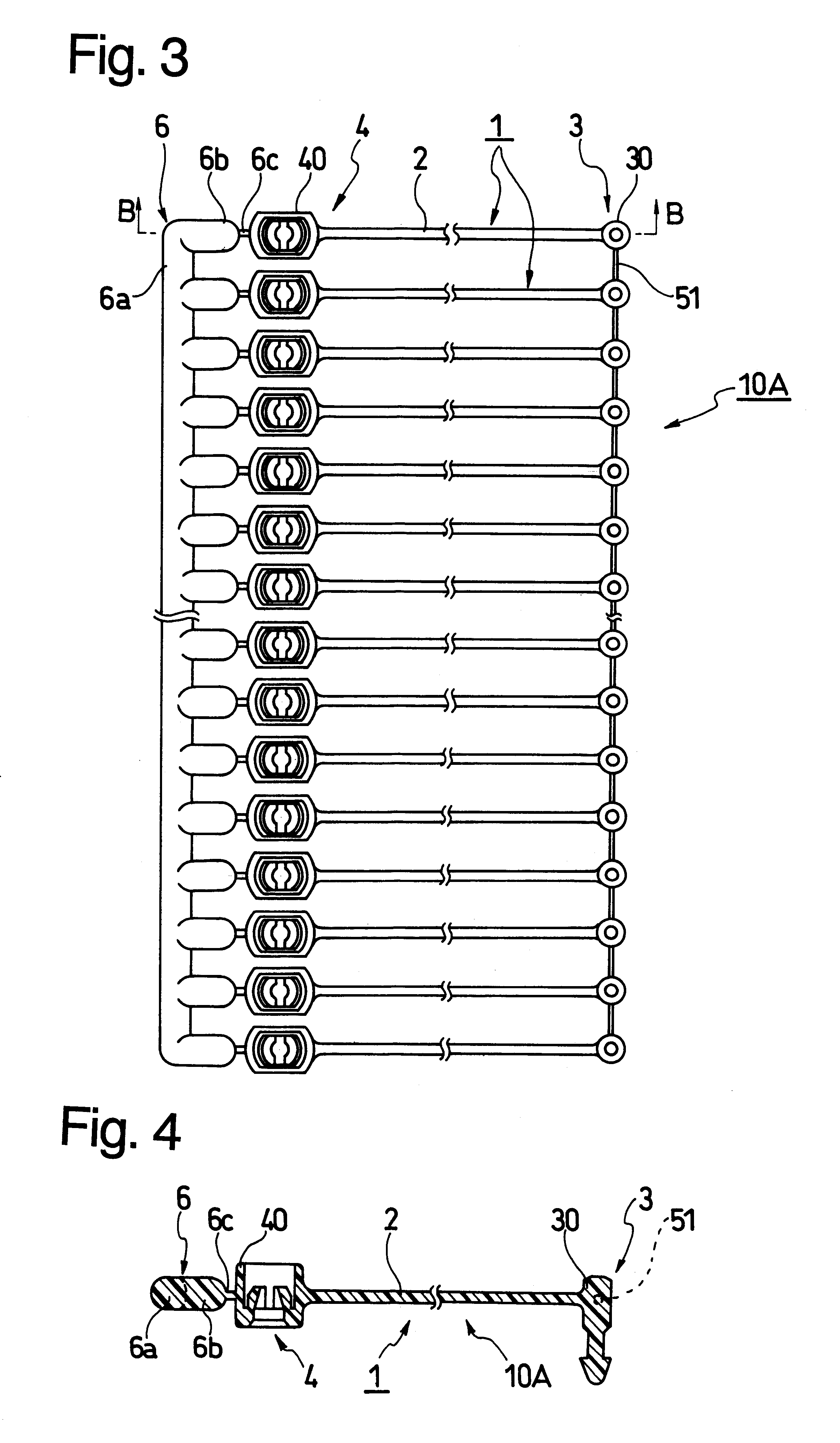
Next in the fastener assembly 10A of a second embodiment shown in FIGS. 3 and 4, the retaining projections 3 are jointed one another at their trunk portions 30 by first temporary joint portions 51 of a thin filament shape having a small section, and the fitting portions 4 are jointed at their frame portions 40 to the second joint member 6 having the second cutting portions 6c formed in the extending direction of the filament portions 2. This second joint member 6 is formed of: a second joint rod 6a having a relatively high rigidity; second projections 6b projecting in the shape of comb teeth from the second joint rods 6a; and second cutting portions 6c leading from the second projections 6b to the frame portions 40 of the fitting portions 4 and formed in the extending direction of the filament portions 2 while being reduced in their sections to be easily cut. The second joint member 6 thus formed is jointed to the fitting portions 4 on the side opposed to the filament portions 2.

Mor...

third embodiment

On the other hand, the fastener assembly 10B of a third embodiment shown in FIGS. 5 and 6 corresponds to the construction having filament portions 2 having a relatively small length and a relatively high rigidity. The trunk portions 30 of the retaining projections 3 are mutually jointed by the first temporary joint portions 51 having a small section, and the frame portions 40 of the fitting portions 4 are mutually jointed by the second temporary joint portions 61 having a small section.

Moreover, the fasteners 1 are jointed by the first temporary joint portion 51 and the second temporary joint portions 61 so that they are arrayed in a sheet shape, and the axes of the retaining projections 3 and the axes of the engaging holes 42 of the fitting portions 4 are formed perpendicular to the arrayed plane of the fasteners 1.

The sizes of the ordinary fastener assembly 10, 10A or 10B will be exemplified in the following. For the aforementioned sizes of the fasteners 1: the distances between c...


PUM

PropertyMeasurementUnit
Angleaaaaaaaaaa
Areaaaaaaaaaaa

Abstract

A fastener assembly which includes a plurality of fasteners each having a retaining projection which has a longitudinal axis, a fitting portion formed with an engaging hole which also has an axis in which the retaining projection can engage, and a filament portion arranged between the retaining projection and the fitting portion. A first joint member is connected with the retaining projections of the fasteners through first cutting portions each having a reduce sectional area. A second joint member is connected with the fitting portions through second cutting portions. In this manner, the fasteners are fixed to and securely supported by the first and second joint members to be arrayed in a plane. The axes of the retaining projections and the axes of the fitting holes of the fitting portions are formed perpendicular to the plane of the fasteners. An attaching device can be simply charged with the fastener assembly in a set and in an array and can be disassembled in the device into individual fasteners so that each of these fasteners is enabled to attach a price tag or label to a commodity with a loop of its filament portion by inserting its retaining projection easily to engage with the fitting portion. In the alternative, the fastener assembly can be manually used by disassembling it easily by hand into individual fasteners and can be held in the array state without any entanglement while it is being transported or stored.

Description

1. Field of the InventionThe present invention relates to a fastener of a synthetic resin to be used for attaching a price tag or label to a commodity while forming a loop of a filament shape or for bundling a plurality of commodities such as slippers, sandals or shoes into one set.2. Description of the Prior ArtAs a joint for attaching a price tag or label to a commodity such as clothes, there has been commonly used a retaining member of a synthetic resin, as called the "tag pin". This retaining member includes a thin, flexible filament portion, a cross bar portion formed perpendicularly on one end of the filament portion, and a flat, board-like head portion formed on the other end of the filament portion, such that it is wholly formed into a shape of letter "H".Since this retaining member is far smaller than the price tag of the commodity, it is necessary to assemble a number of retaining members into one set so that they may be conveniently manufactured and handled. In order to h...

Claims


Application Information

Patent Timeline
IPC IPC(8): B65D63/10G09F3/08G09F3/14
CPCB65D63/1081G09F3/14B65D2563/102B65D2563/105Y10T24/1498Y10T24/153Y10T24/4691Y10T292/496Y10T292/499
Inventor KUBOTA, MIKIOSUZUKI, TADASHI
Owner TOSKA
Why Eureka
Try Eureka