Airlift

a technology of airlifting and liquid, applied in the direction of machines/engines, jet pumps, machines/engines, etc., can solve the problems of low lifting efficiency and significant fluctuations in liquid and air flow, and achieve the effect of increasing airlifting efficiency

Inactive Publication Date: 2001-04-24
KHUDENKO BORIS MIKHAILOVICH
View PDF3 Cites 18 Cited by
  • Summary
  • Abstract
  • Description
  • Claims
  • Application Information

AI Technical Summary

Benefits of technology

The airlift comprises a lift pipe having a suction port, a discharge port, an air feed, and means for inducing rotational motion of liquid at the discharge port. The rotational motion can be provided by at least one inclined baffle, at least one curved two-dimensional baffle, at least one tri-dimensional baffle, and combinations thereof. Such rotational motion plays a role of a fly wheel in mechanical systems, thus increasing the airlifting efficiency. Additionally, air is separated from the liquid more gradually without forming air pockets. Accordingly, splashing and heisering due to bursting air pockets are eliminated.

Problems solved by technology

The main problem of airlifts is significant fluctuations in flows of liquid and air.
This results in low lifting efficiency.
Moreover, fluctuating flows and poorly organized separation of liquid and gas produce splashes and heisering, which is an operational nuisance.

Method used


Image

  • Airlift
  • Airlift
  • Airlift

Examples


Embodiment Construction

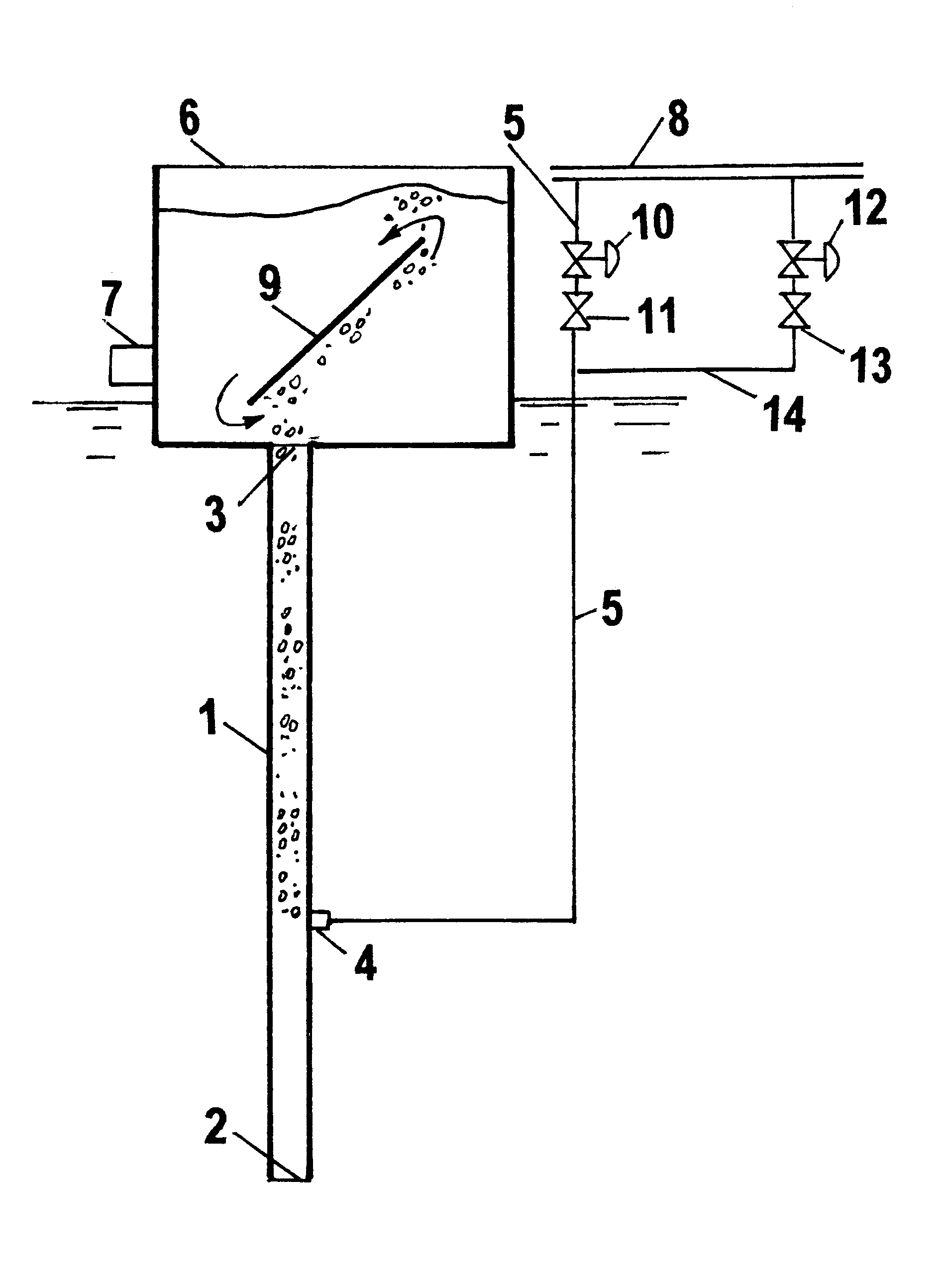
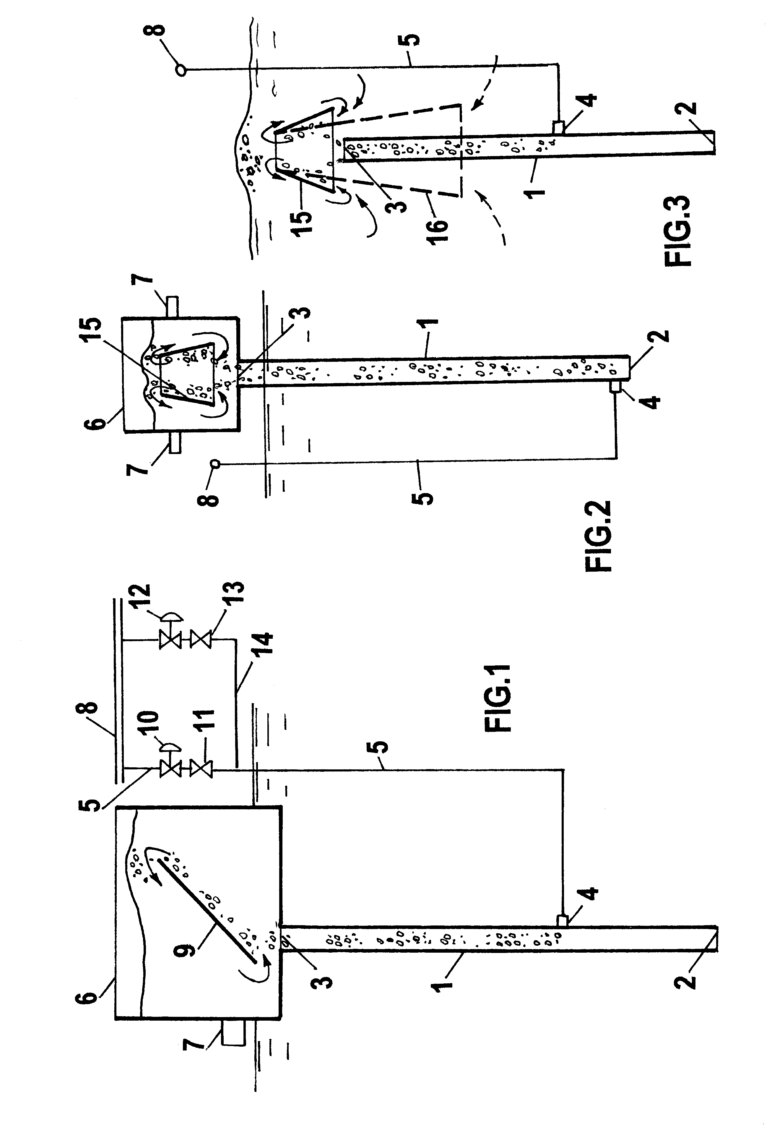
Referring now to FIG. 1, there is shown an airlift comprising a lift pipe 1 having a suction port 2 and disharge port 3, an air main 8 connected to the lift pipe 1 at a port 4. A container 6 is attached to the lift pipe at the port 3. This container has a liquid discharge means 7 and a baffle 9 for inducing flow rotations above the port 3. Optionally, control valve 11 and on / off valve 10 are provided on an air branch 5. Additionally, at least one more optional branch 14 with control valve 13 and on / off valve 12 can also be provided.

Referring now to FIG. 1, the airlift is operated as follows. The air is fed via main 8 and branches 5 and 14 into the lift pipe 1 submerged in liquid. An air-liquid mixture is formed. This mixture has lower density than the non-aerated liquid outside the pipe 1. Accordingly, it floats up in the lift pipe, exits from the port 3 and reaches the flat inclined baffle 9. On the lower (right side in FIG. 1) side of the baffle, the air-liquid mixture continues t...


PUM


Abstract

A method for lifting liquids with airlift consisting of a lift pipe having a suction port, a discharge port, and an air feed including steps of (a) feeding air into the lift pipe, (b) sucking liquid in the suction port, (c) discharging liquid and air at the discharge port, and (d) inducing rotational motion of liquid at the discharge port, whereby the efficiency of said airlift is increased and splashing and heisering are eliminated. An airlift apparatus with means for inducing rotational motion at the discharge port is also provided. The means for inducing rotations can be an inclined flat or curvilinear baffle.

Description

The invention belongs to methods and apparatus for lifting aqueous and non-aqueous liquids, suspensions, and emulsions with the help of air or other gases.Airlifts are well known in the prior art. Air is used in airlifts. Other gases are used in gaslifts. In the present invention, these terms are used interchangeably. The main problem of airlifts is significant fluctuations in flows of liquid and air. This results in low lifting efficiency. Moreover, fluctuating flows and poorly organized separation of liquid and gas produce splashes and heisering, which is an operational nuisance.The main objective of this invention is to eliminate flow fluctuations thus increasing the pumping efficiency of airlifts and to eliminate splashing. Other objectives of this invention will become apparent from the ensuing description.SUMMARY OF INVENTIONThis is a method for lifting liquids with airlift consisting of a lift pipe having a suction port, a discharge port, and an air feed including steps of(a)...

Claims


Application Information

Patent Timeline
Patent Type & Authority Patents(United States)
IPC IPC(8): F04F1/00F04F1/18
CPCF04F1/18
Inventor KHUDENKO, BORIS MIKHAILOVICH
Owner KHUDENKO BORIS MIKHAILOVICH
Why Eureka
Try Eureka