
Multiphase power supply with series connected power cells with failed cell bypass

a power supply and series connection technology, applied in the direction of dc-ac conversion without reversal, switch power arrangement, contact mechanism, etc., can solve the problems of unbalanced output, inoperable drive, imbalanced line conditions,

Inactive Publication Date: 2001-04-24
SIEMENS ENERGY & AUTOMATION INC
View PDF20 Cites 97 Cited by
  • Summary
  • Abstract
  • Description
  • Claims
  • Application Information

AI Technical Summary

Benefits of technology

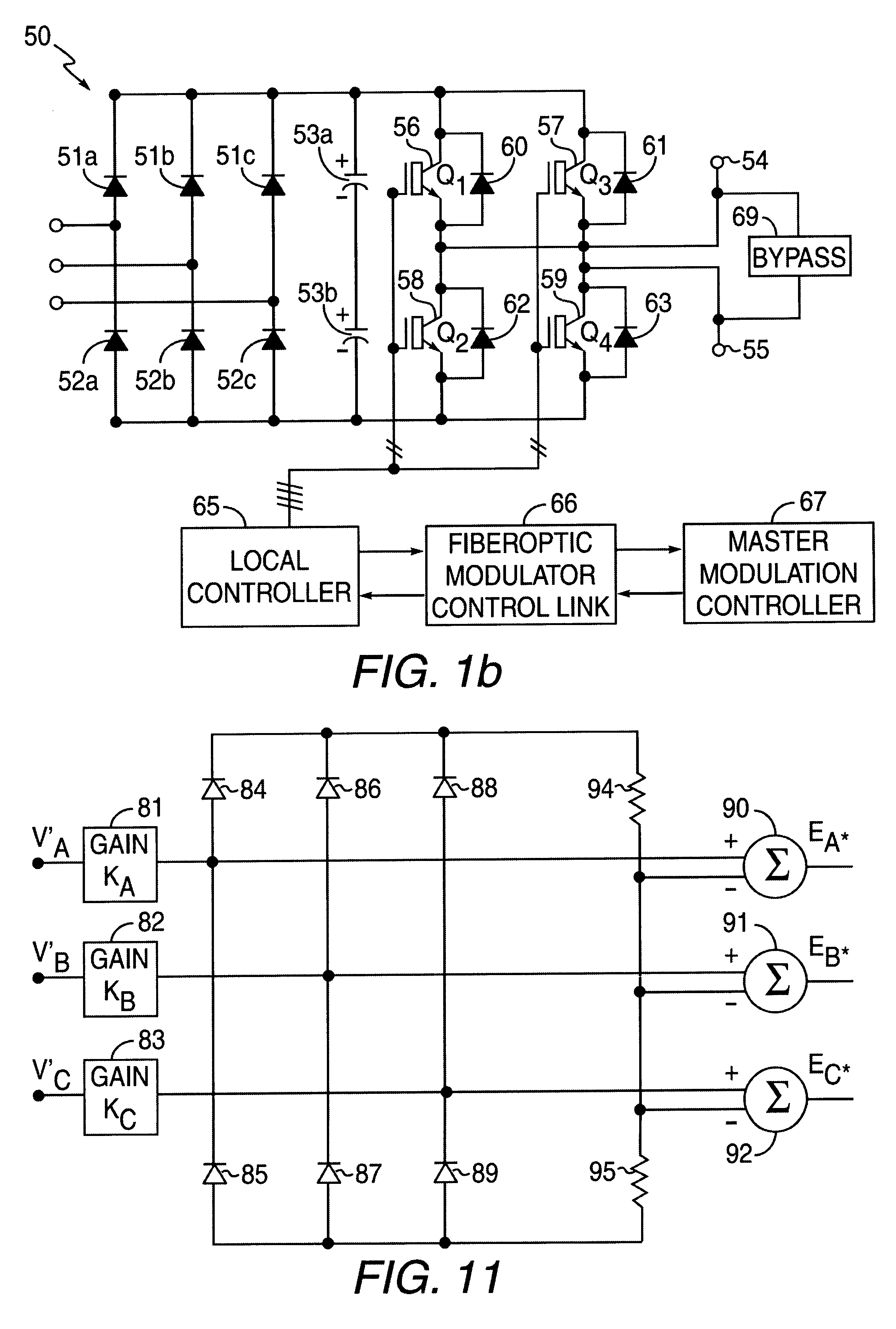
The invention is directed to a method of operating a multiphase power supply that has a plurality of cells or converters connected in series in each of a plurality of legs. This results in each leg having a leg voltage equal to the sum of connected cells in such leg. In addition, the power supply has a line-to-line voltage output between the terminal ends of each pairs of legs. This invention applies to loads that are not connected to the common leg junction, but only to the end points of the legs, so that only the line-to-line output voltage appears on the load. During a failed condition in which any one or number of cells have failed in any of the legs, the line-to-line voltage output is maximized. This is done by detecting failed cells in any of the legs and forming a current path around such failed cell by an electrical bypass. As a result no voltage component from the failed cell is included within the leg in which it previously was connected. The outputs of the unfailed cells are controlled so as to maximize the line-to-line voltage in the output of the power supply so that their magnitudes are generally equal. By so regulating their outputs, the line-to-line phase voltages of the output of the power supply can be balanced. In a three-phase output supply without failed cells, balanced voltage is maintained by having a 120.degree. phase relationship between the leg output voltages. The line-to-line phase balance can be restored by adjusting the leg-to-leg phase relationship between the respective legs when failed cells are detected. Circuitry is provided to implement a method for reducing the peak voltage demands between legs. Voltage command signals can be generated to provide peak voltage reduction, and such signals can be modified to compensate for the detection of failed cells. The modification can be a gain control using a gain which is proportional to the ratio of the total number of cells in the leg (including failed cells) divided by the number of active cells (not bypassed) in the leg. The invention is particularly adapted to pulse width modulated serial converters in each leg. The result is balanced line-to-line output from the power supply and full utilization of each unfailed cell in the system.

Problems solved by technology

However, should a given cell in a series arrangement fail during operation, that current path can become open-circuited, rendering the entire drive inoperable.
This can then result in an unbalanced output, in that the leg having the shorted cell must operate at less than full voltage.
Such operation can create imbalanced line conditions and be damaging to load elements.
However, it still represents a substantial reduction in the output speed and power available from the drive.
By shunting out or bypassing two operational power cells such as B.sub.1 and C.sub.1 in the example, these power cells can no longer contribute to the output power available to the load.

Method used


Image

  • Multiphase power supply with series connected power cells with failed cell bypass
  • Multiphase power supply with series connected power cells with failed cell bypass
  • Multiphase power supply with series connected power cells with failed cell bypass

Examples


Embodiment Construction

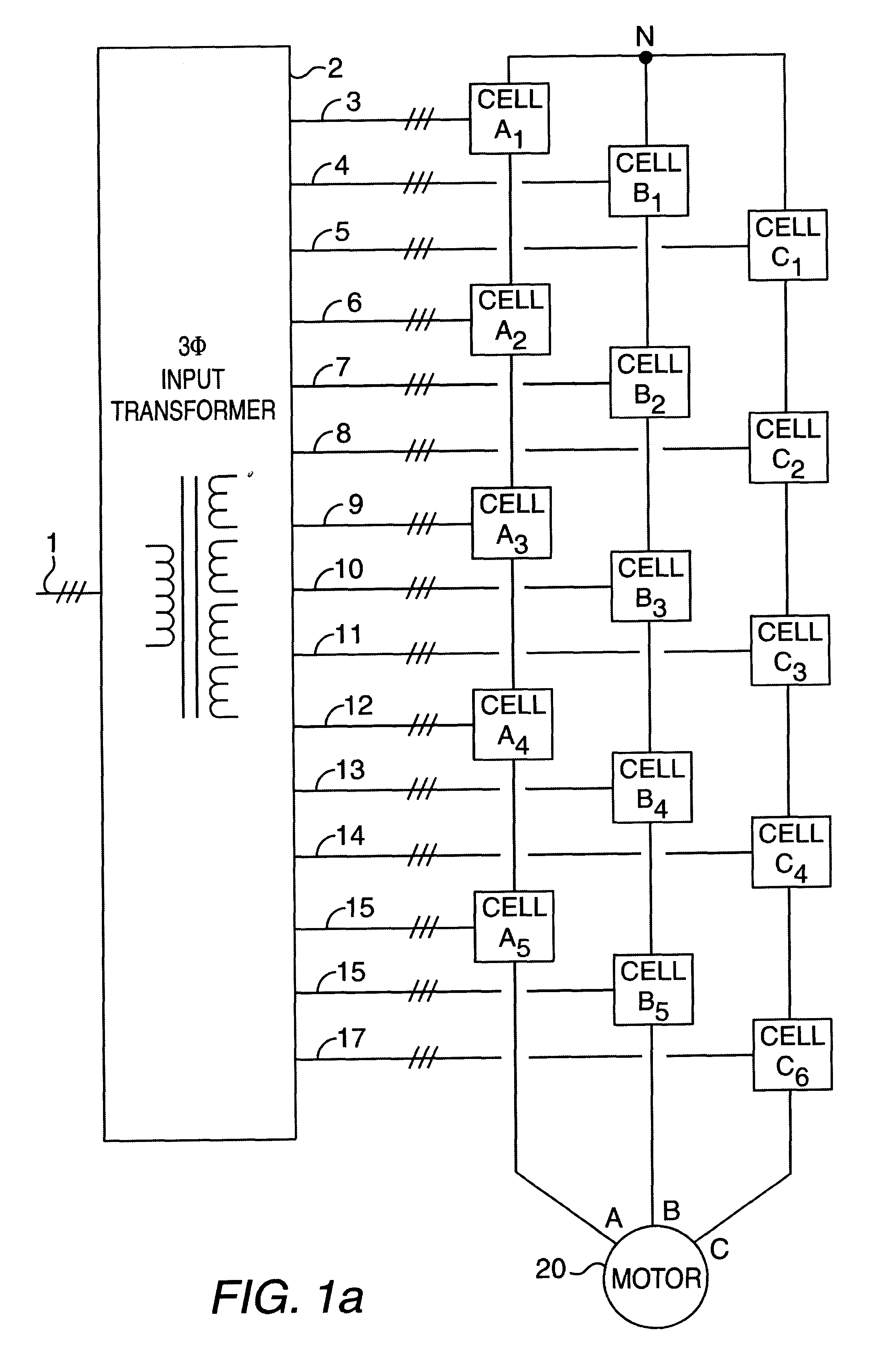
FIG. 1a shows a power circuit diagram for an AC drive. This is a typical arrangement in which the invention can be utilized, however, other drives and power supplies can also utilize the apparatus and method of this invention. A three-phase incoming line 1 feeds into a power transformer 2. As shown, power transformer 2 may be of any configuration, and in some preferred embodiments will be the multiple winding three-phase isolation transformer as shown in U.S. Pat. No. 5,625,545. Such a transformer may have a primary winding which is star or mesh connected, which is energized from the three-phase incoming line 1. The transformer may then energize a number of single or multi-phase secondary windings. In presently preferred embodiments, there will be a number of secondary windings each corresponding to a respective converter or power cell in the drive. It is also preferred that the windings be preselected to certain degrees of electrical phase such as taught in the aforementioned paten...


PUM


Abstract

A high output level is maintained in power supplies having multiple cells in each leg. Failed cells in any leg are bypassed to provide a current path through the respective leg. All of the unfailed cells are utilized while maintaining equal magnitude between phases and a balance phase relationship in the line-to-line output voltage. The invention may be utilized in conjunction with a peak voltage reduction circuit, and a by-pass switch.

Description

I. Field of the InventionThis invention relates to a drive and specifically a drive and a method for operating a variable drive such as a variable-speed motor drive system.II. Description of Prior ArtVariable-output drives traditionally are used in industry to provide variable electric power to AC motors. These same drives can be used in other applications not related specifically to motors but where a variable-output voltage or frequency is desired. Typical drives have an AC input power source and some type of conversion apparatus, usually using solid-state devices, for converting the fixed AC input voltage into a variable-voltage and / or variable-frequency output. One such type of drive is described in U.S. Pat. No. 5,625,545, which is incorporated herein by reference. That patent describes a power supply used as a drive which utilizes a number of power cells arranged to produce a three-phase AC output. Such multiple power cells in series can be utilized to provide higher voltage o...

Claims


Application Information

Patent Timeline
Patent Type & Authority Patents(United States)
IPC IPC(8): H02M7/48H02M1/00H02M7/49
CPCH02M7/49B60L15/007H02M2007/4835H02M2001/325Y02T10/64H02M1/325
Inventor HAMMOND, PETER W.AIELLO, MARC F.
Owner SIEMENS ENERGY & AUTOMATION INC
Learn More