Pattern inspecting method and pattern inspecting device

a technology of pattern inspection and inspection method, applied in the field of pattern inspection method, can solve the problems of individual variations of inspection standard, low inspection efficiency, and insufficient high-quality inspection

Inactive Publication Date: 2001-04-24
MATSUSHITA ELECTRIC WORKS LTD
View PDF10 Cites 58 Cited by
  • Summary
  • Abstract
  • Description
  • Claims
  • Application Information

AI Technical Summary

Problems solved by technology

However, since over-detection of defects frequently occurs, confirmation is needed after the automatic inspection.
However, due to the visual inspection by human, there are problems such as a low inspection efficiency and individual variations in inspection standard.
However, since careful consideration is not given to the preparation of the reference data, it is not sufficient to provide high inspection accuracy.

Method used


Image

  • Pattern inspecting method and pattern inspecting device
  • Pattern inspecting method and pattern inspecting device
  • Pattern inspecting method and pattern inspecting device

Examples


Embodiment Construction

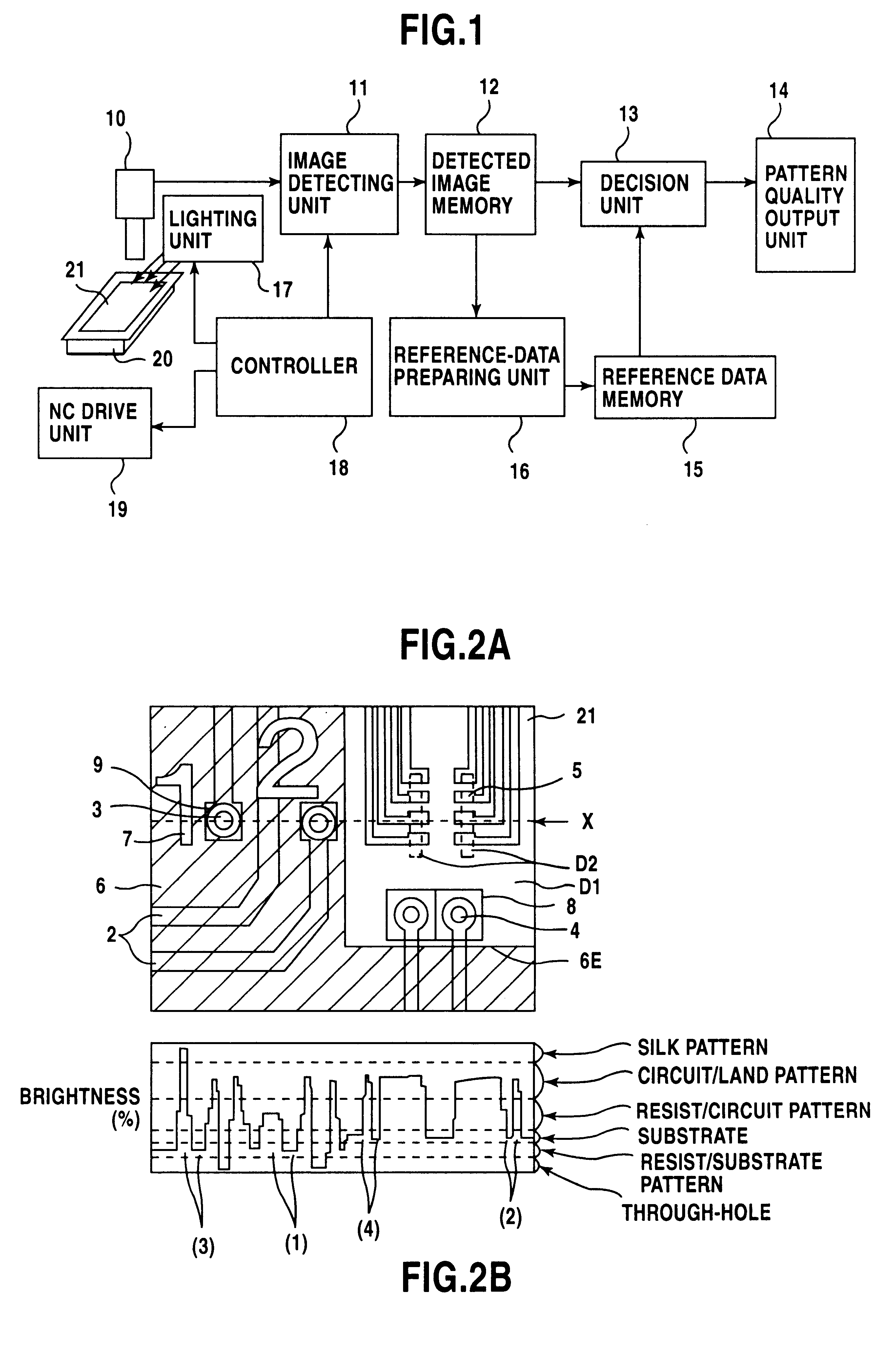
As shown in FIG. 1, a pattern inspection apparatus of the present invention comprises a line sensor 10, image-detecting unit 11, detected-image memory 12, decision unit 13, pattern-quality output unit 14, reference-data memory 15, reference-data preparing unit 16, lighting unit 17, controller 18 for lighting and image-taking conditions, NC drive unit 19, and a NC table 20.

A substrate 21 having a reference pattern or an inspection pattern to be inspected is placed on the NC table 20. The NC drive unit 19 is used to move the substrate 21 in a Y-axis direction in synchronization with the line sensor 10. If necessary, an XY.theta.-axes fine adjustment mechanism for positioning the substrate 21 may be used. The line sensor 10 can take an image of the substrate 21 on the NC table 20, while interlocking with the Y axis movement of the substrate. The lighting unit 17 provides illumination to obtain a good image of the substrate. The control unit 18 controls a switching between a single ligh...


PUM

PropertyMeasurementUnit
sizeaaaaaaaaaa
widthaaaaaaaaaa
roughnessaaaaaaaaaa

Abstract

A pattern inspection method capable of providing an improved inspection reliability includes the following steps. A pattern classification is set every pixel-value range of a reference-image data obtained from a reference pattern. Each of the pattern classifications has reference-data preparing parameters. With respect to each pixel of the reference-image data, pixel values of a pixel window which is composed of the pixel as a center pixel and neighbor pixels around the center pixel are checked to prepare a reference data. When all of the pixels in the pixel window are within a single pixel-value range, the center pixel is decided as a pattern uniform portion, and the reference data is prepared according to the parameters of a corresponding pattern classification. When all of the pixels in the pixel window are not within the single pixel-value range, the center pixel is decided as a pattern step portion, and internal and external pattern classifications are determined, so that the reference data is prepared according to the parameters of at least one of the internal and external pattern classifications. An inspection-image data of a pattern to be inspected is compared with the reference data to detect a defect of the pattern.

Description

This is a Continuation-in-Part of International Application PCT / JP98 / 02838 with an international filing date of Jun. 25, 1998.1. Field of the InventionThe present invention relates to a pattern inspection method of inspecting patterns of printed wiring boards, printed circuit boards, or the other articles with patterns, and an apparatus therefor.2. Disclosure of the Prior ArtPrinted wiring boards or printed circuit boards are usually manufactured through a plurality of manufacturing stages. As an example, a plan view of a printed wiring board is shown in FIG. 23. In a first stage, circuit patterns 2 are formed on substrates 1, and also through holes 3 or via-holes 4 are formed. In a second stage, a metal such as gold is plated on IC connecting pads 5, and solder-resist patterns 6 or silk-printing patterns (letter 7 and mark 8) are formed. In FIG. 23, the numeral 6E designates an edge of the solder-resist pattern 6.In the first stage, defects such as short circuit, chipping, projecti...

Claims


Application Information

Patent Timeline
Patent Type & Authority Patents(United States)
IPC IPC(8): G01N21/956G01N21/88
CPCG01N21/95607G01N2021/95615G01N2021/95638
Inventor OKAMOTO, SHINJI
Owner MATSUSHITA ELECTRIC WORKS LTD
Why Eureka
Try Eureka