Plug housing with attached cantilevered latch for a fiber optic connector

a technology of cantilevered latch and plug housing, which is applied in the direction of optics, instruments, optical light guides, etc., can solve the problems of wire damage or some portion of the connector becoming damaged, and achieve the effect of not being prone to breakage during us

Inactive Publication Date: 2001-05-01
COMMSCOPE TECH LLC
View PDF13 Cites 80 Cited by
  • Summary
  • Abstract
  • Description
  • Claims
  • Application Information

AI Technical Summary

Benefits of technology

Another object of the present invention is to provide a plug housing having a novel latch structure thereon in a connector, such connector being used to terminate an optical fiber, and such latch structure not being prone to entanglement wi

Problems solved by technology

Entanglement with wires during connection or disconnection of a connector can prov

Method used


Image

  • Plug housing with attached cantilevered latch for a fiber optic connector
  • Plug housing with attached cantilevered latch for a fiber optic connector
  • Plug housing with attached cantilevered latch for a fiber optic connector

Examples


first embodiment

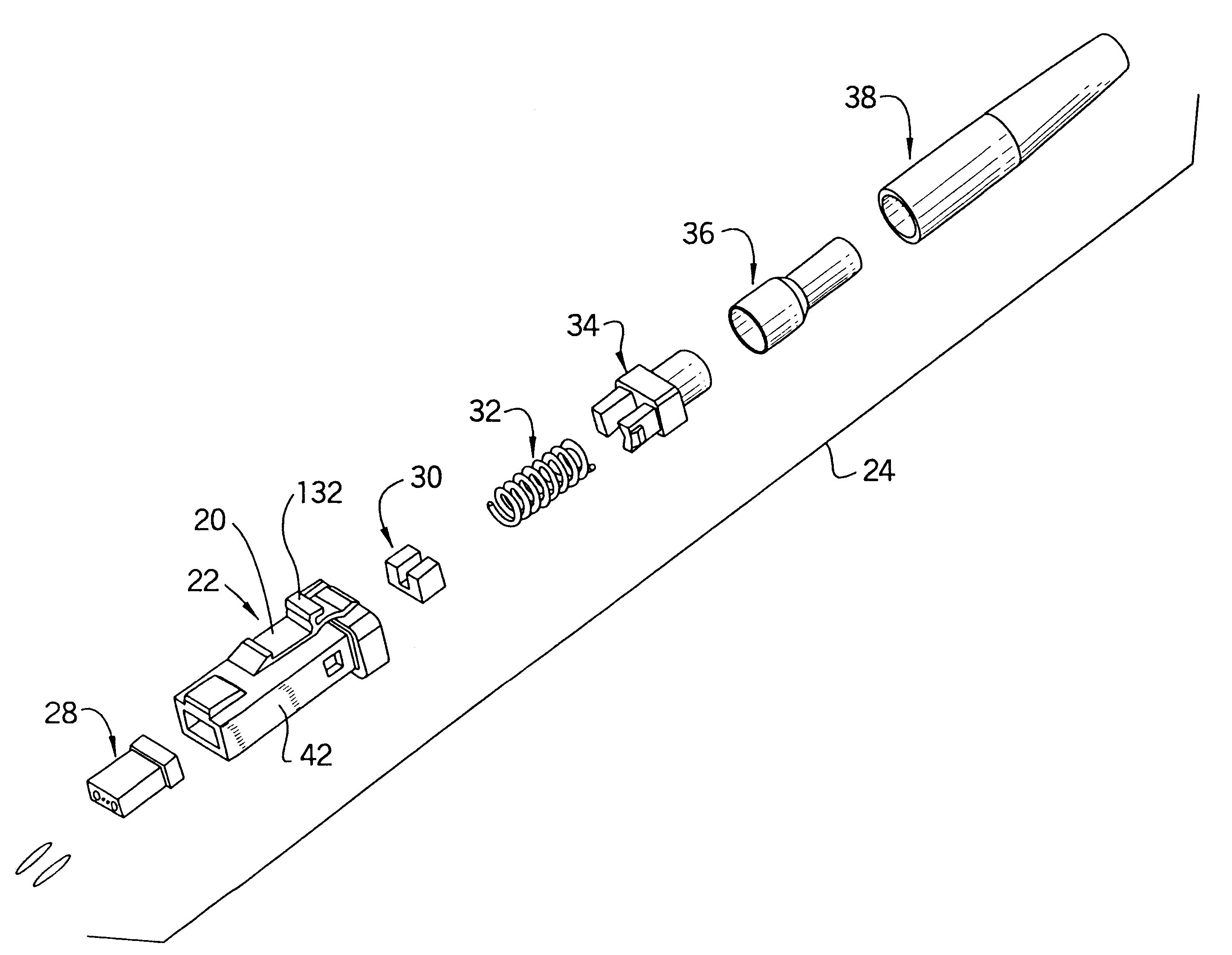
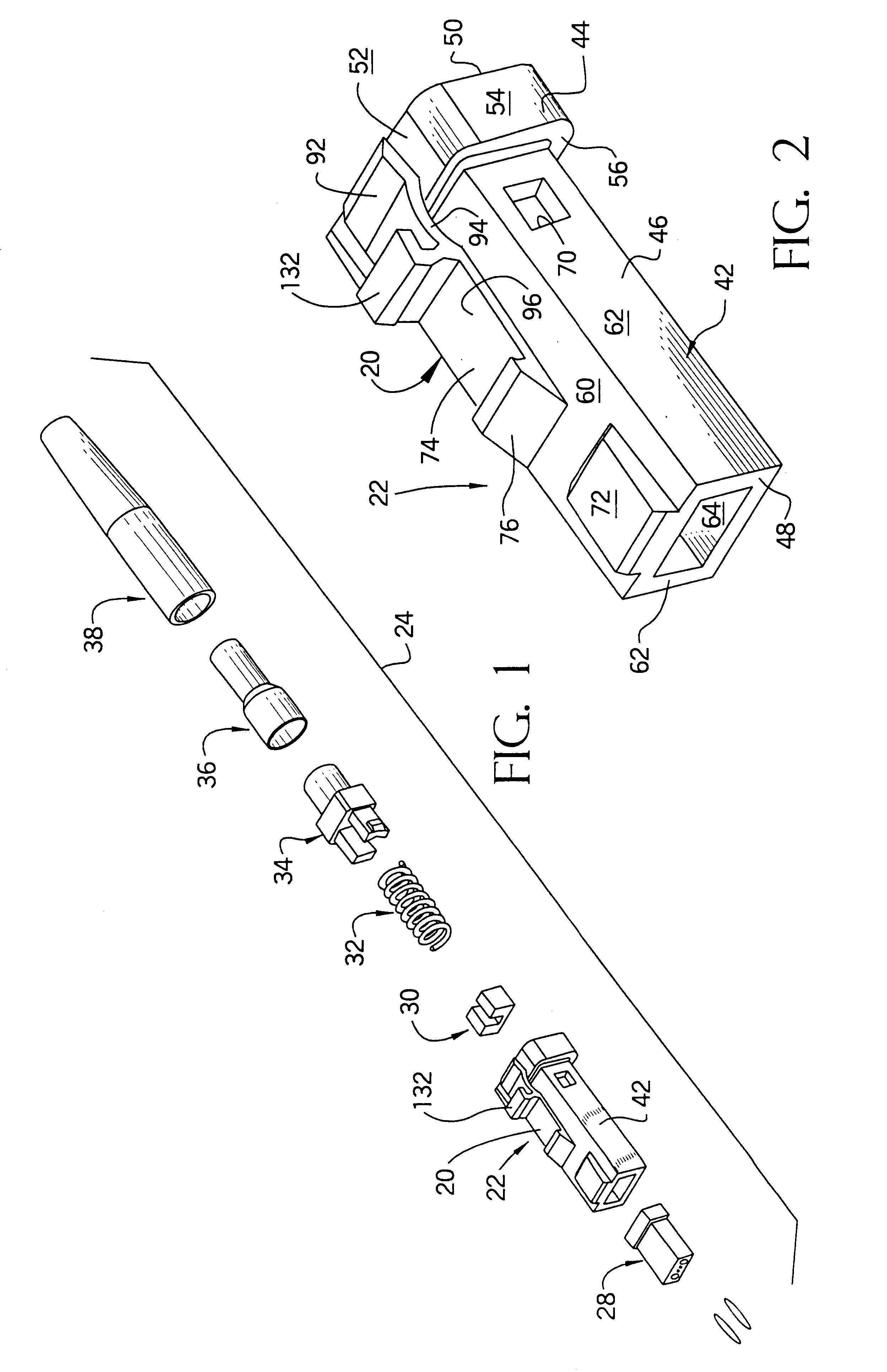
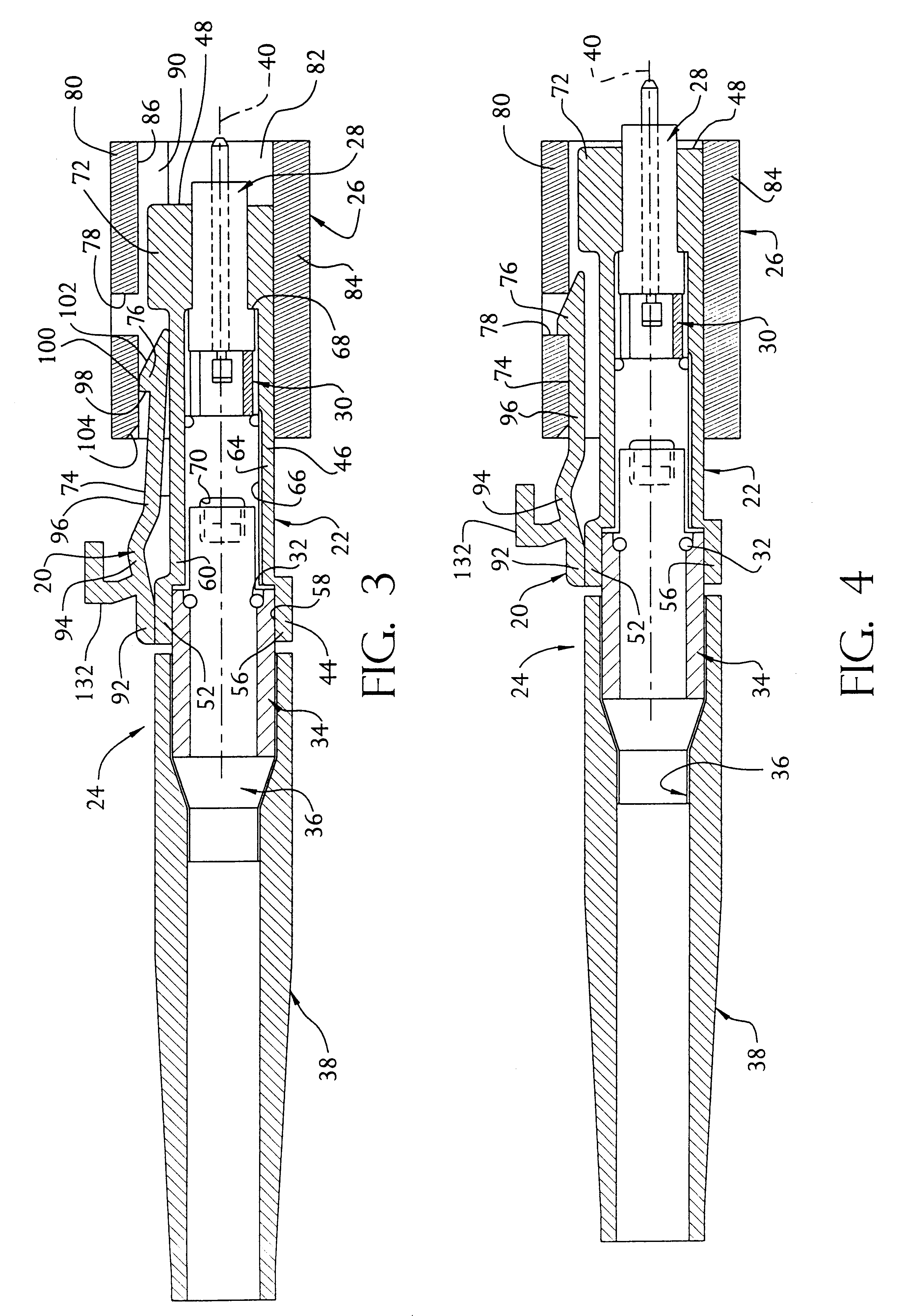
Attention is now directed to FIGS. 2, 5 and 7 for an explanation of the structure of the plug housing 22, 22a, 22b. For ease in description, the general structure of the plug housing 22, 22a, 22b, with the exception of the novel latch structure 20, 20a, 20b, is described with respect to the plug housing 22 shown in FIGS. 1-4 with the understanding that the other embodiments of the plug housing 22a, 22b are the same. The plug housing 22 is formed from a thermoplastic member 42 which includes a base portion 44 integrally formed with a portion 46 which extends therefrom. A front end of the plug housing 22 is defined at 48 and a rear end of the plug housing 22 is defined at 50. The terms "forward" and "rearward" are defined in this manner because the forward end of the plug housing 22 is defined as the end which is first inserted into the receptacle 26.

The base portion 44 has a top wall 52, opposite side walls 54 (only one of which is shown) and a bottom wall 56. The top and bottom wall...

third embodiment

Attention is now directed to FIGS. 7 and 8 which illustrates the plug housing 22b which has the low profile latch structure 20b thereon, and the receptacle 26b in which the connector 24b is mounted.

The receptacle 26b is rectangular-shaped and has a top wall 80b, opposite side walls 82b and a bottom wall 84b. The top and bottom walls 80b, 84b are spaced from each other and the side walls 82b are spaced from each other so as to define a rectangularly-shaped axial passageway 86b which extends through the receptacle 26b. The retention structure 78b is formed as a pair of rectangularly-shaped retention protrusions (only one of which is shown in the cross-sectional view of FIG. 8) are provided in the passageway 86b at predetermined positions. The retention protrusions 78b extend from the top wall 80b into the passageway 86b. A keyway 90b is provided in a forward end of the receptacle passageway 86b.

The latch structure 20b, like that of the first and second embodiments, is formed from a fo...


PUM


Abstract

A novel forward-facing, aft-attached cantilever beam is provided as a latch for securing a fiber optic connector to a receptacle. The beam has engagement structure on its free end which attaches to the receptacle. The connector includes a plug housing formed from a member having a forward end and a rearward end and an axial passageway therethrough through which at least one optical fiber provided in the fiber optic cable extends. The forward end is inserted into the receptacle with the rearward end extending from the receptacle. The cantilevered beam has an end fixed to a rearward portion of the member and its free end extends forwardly toward the forward end of the member. To engage the connector with the receptacle, the free end of the cantilevered beam is biased toward the member and the member is slid into the receptacle. Once fully inserted, the engagement structure on the cantilevered beam engages retention structure in the receptacle. The connector can be released from engagement with the receptacle by biasing the cantilevered beam such that the engagement structure on the beam is released from the retention structure of the receptacle and thereafter pulling the connector out of the receptacle.

Description

The present invention relates generally to connectors preferably for use with fiber optics, and more specifically relates to a novel latch structure for mounting a connector to a receptacle.Fiber optic technology presents several advantages which cannot be provided by other technologies. For example, fiber optic communication systems provide immunity from electromagnetic interference (EMI), provide virtually unlimited bandwidth, and provide that data can be quickly transferred over long distances.Typically, connectors are used within optical fiber communication systems. For example, connectors are used to join optical fibers together to form a longer length or to connect an optical fiber to a device. Generally, a connector must provide that the end of one optical fiber becomes axially aligned with the end of another optical fiber. As a result, after the connection is made, all of the light from one optical fiber can travel into the other optical fiber. Because optical fibers are ext...

Claims


Application Information

Patent Timeline
IPC IPC(8): G02B6/38
CPCG02B6/3893G02B6/3821G02B6/3869G02B6/3887G02B6/3888G02B6/38875
Inventor MANNING, RANDY MARSHALLEDWARDS, BRYAN THOMASBUCHTER, SHELLY ANNBRIGGS, ROBERT CARL
Owner COMMSCOPE TECH LLC
Why Eureka
Try Eureka