Fluid pump without non-return valves

a technology of non-return valve and pump, which is applied in the direction of positive displacement liquid engine, piston pump, liquid fuel engine, etc., can solve the problems of high expenditure, low maximum pumping efficiency, and range of 10 to 20%

Inactive Publication Date: 2001-05-08
EPPENDORF AG
View PDF11 Cites 145 Cited by
  • Summary
  • Abstract
  • Description
  • Claims
  • Application Information

AI Technical Summary

Benefits of technology

In addition, the present invention is based on the finding that it is possible to provide a self-priming fluid pump, e.g. a self-priming micropump, by drastically reducing the dead volume developing in the micropump, i.e. the volume which is only moved to and from without contributing to the pumping process. Autofilling in combination with a simple control of the pump drive means becomes reproducible in this way.

Problems solved by technology

When the pumping direction of such an arrangement is to be reversed, such known pumps require a change of the operating direction of the valves from outside which entails a high expenditure.
One disadvantage of this embodiment is to be seen in the fact that, upon constructing the valves, a compromise has to be found between the mechanical resonance in the liquid surroundings, the flow resistance, the fluidic capacity, i.e. the elastic volume deformation, the constructional size and the mechanical stability of these valves.
It follows that these parameters, each of which may influence the pumping dynamics, cannot be ajusted to an optimum value independently of one another and part of them is opposed to a desired further miniaturization of the pump dimensions.
A general disadvantage entailed by the use of pumps with passive check valves is also the fact that, when switched off, the pumps do not block the medium to be transported.
Micropumps using special flow nozzles have the disadvantage that they have a very low maximum pumping efficiency in the range of 10 to 20%.

Method used


Image

  • Fluid pump without non-return valves
  • Fluid pump without non-return valves
  • Fluid pump without non-return valves

Examples


first embodiment

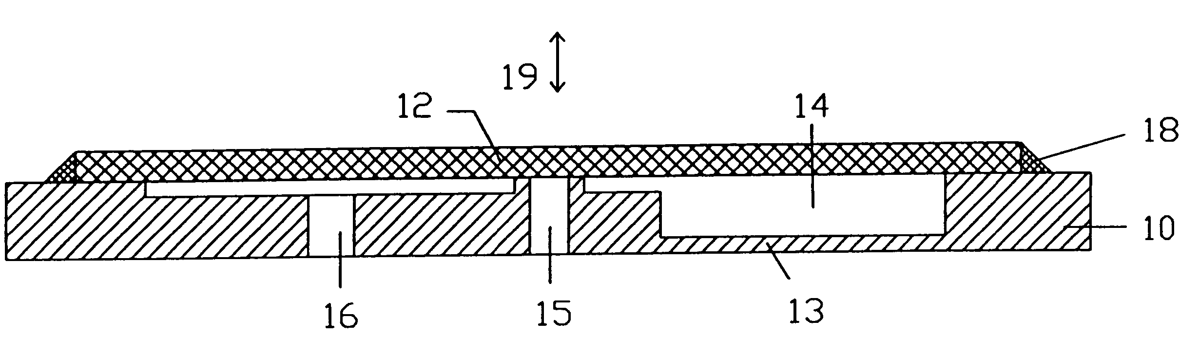
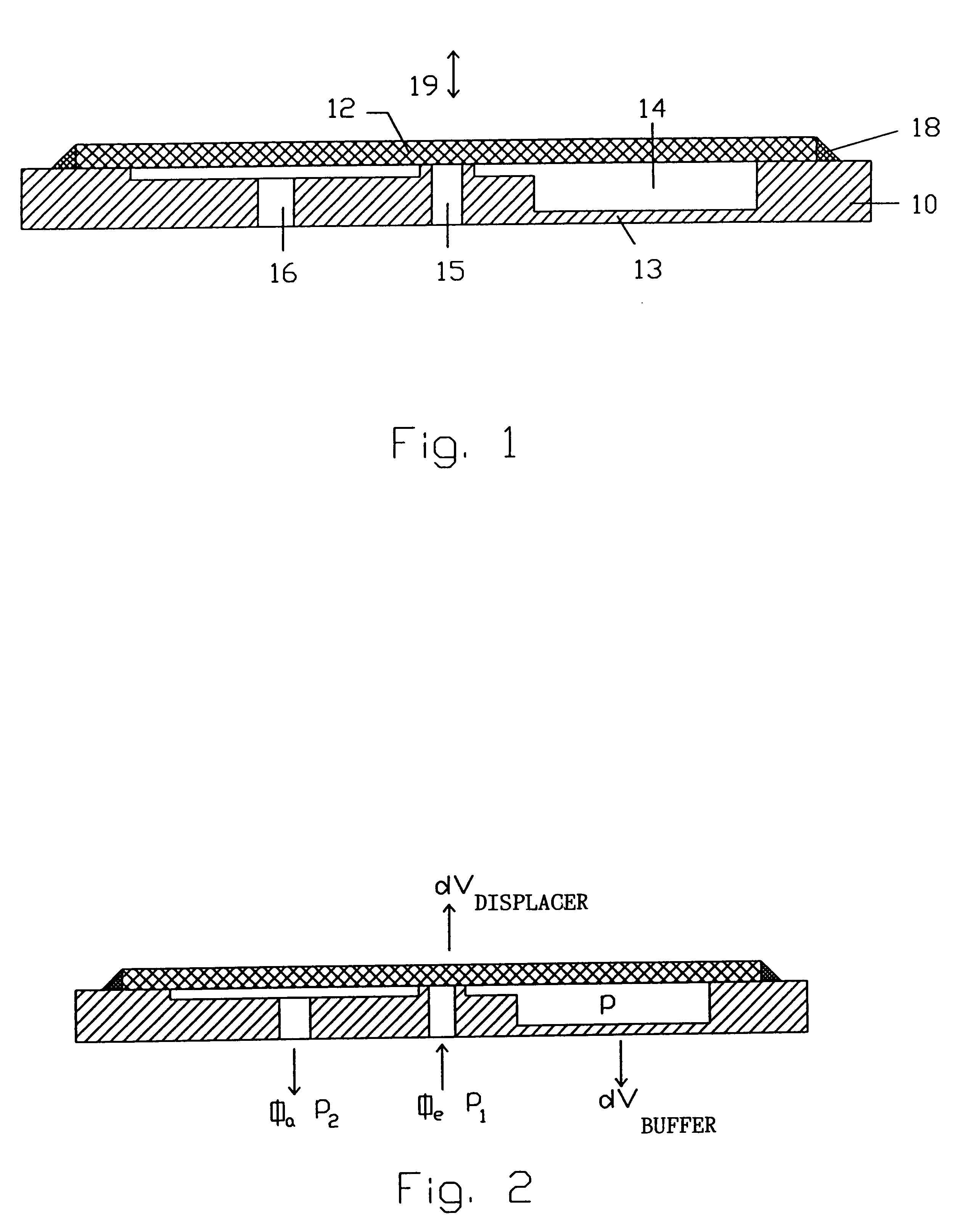
Let us assume that the hydrostatic pressure p1 prevails on the inlet side, the hydrostatic pressure p2 on the outlet side and the pressure p in the pump chamber. The flow rate through the two openings is referred to as .phi..sub.e for the inlet opening 15 and .phi..sub.a for the outlet opening 16. The displacer, whose position of rest corresponds to the first end position at which the inlet opening is closed in accordance with the first embodiment, is moved to its second end position by actuating the drive means, whereby the volume of the pump chamber is changed by a defined volume amount dV*. A pressure-dependent volume displacement of the elastic buffer is referred to as V.sub.buffer. It is positively weighted when the diaphragm 13 bulges out of the pump chamber 14 and negatively weighted when said diaphragm is deformed into the interior of said pump chamber 14.

The volume of the pump chamber is consists of a basic volume V.sub.0 of the pump chamber 14, the deflection of the displa...

third embodiment

FIG. 6 shows a further fluid pump. A pump body 50 of this third embodiment has the same structural design as the pump body 40 of the pump shown in FIG. 5, with the exception that the elastic buffer is not formed in said pump body. The pump body 50 has again arranged therein a displacer 52 which is adapted to be moved like a piston in the direction of arrow 19. When seen in a cross-sectional view, the displacer 52 has the shape of an H, one leg of said H being provided with a projection 52a used for closing an inlet opening 55 in the pump body 50. An outlet opening 56 in the pump body 50 is always open. The displacer 52 is implemented such that it is adapted to close the pump body 50 towards the open side thereof. Depending on the shape of the pump body 50, said displacer can have an arbitrary round, polygonal, elliptical, etc., shape.

On the basis of the shape of the displacer 52, a pump chamber 54 is again defined between the displacer 52 and the pump body 50. In contrast to the pum...

second embodiment

FIG. 9 shows a pump according to the present invention.

In this embodiment, the displacer 82 is part of a second pump body 90. The second pump body 90 is structured, i.e. it is provided with portions of increased thickness and with portions of reduced thickness 89 so as to provide an elastic suspension for the displacer 82. The second pump body 90 is secured to a pump body 80 via connections 88. The pump chamber 84 is formed as a capillary gap between the pump body 80, the displacer 82 and the second pump body 90. The pump body 80 is provided with an inlet opening 85 which is closed by the displacer 82 when said displacer occupies the first end position. The displacer 82 can again be moved in the direction of arrow 19. The second pump body 90 is provided with two outlet openings 86a and 86b. The buffer of this embodiment is again implemented as a diaphragm located in said pump body 80.

In accordance with an alternative embodiment, the buffer could be realized by the portions of reduce...


PUM


Abstract

A fluid pump has a pump body and a displacer which is adapted to be positioned at a first and at a second end position by means of a drive, the displacer and the pump body being implemented such that a pump chamber is defined therebetween, and the pump chamber being adapted to be fluid-connected to an inlet and to an outlet via a first opening and a second opening which are not provided with check valves. An elastic buffer bordering on the pump chamber is provided. The displacer is implemented in the form of a plate which is secured to the pump body, and the pump body is provided with a recess defining the pump chamber. The drive acts on the displacer substantially in the area of the first opening. The displacer closes the first opening when it occupies its first end position and leaves the first opening free when it occupies its second end position. The drive means moves the displacer so abruptly from the second to the first end position that a deformation of the buffer means is caused by the movement of the displacer.

Description

1. Field of the InventionThe present invention refers to fluid pumps.2. Description of Prior ArtIt is known to use positive-displacement pumps for transporting liquids and gases, said positive-displacement pumps consisting of a periodic displacer, a piston or a diaphragm, and two passive check valves. Due to the periodic movement of the piston or of the diaphragm, liquid is drawn into a pump chamber through the inlet valve and displaced from said pump chamber through the outlet valve. The direction of transport is predetermined by the arrangement of the valves. When the pumping direction of such an arrangement is to be reversed, such known pumps require a change of the operating direction of the valves from outside which entails a high expenditure. Such pumps are shown e.g. in Jarolav and Monika Ivantysyn; "Hydrostatische Pumpen and Motoren"; Vogel Buchverlag, Wurzburg, 1993.Pumps of this type having a small constructional size and delivering small pumped streams are referred to as ...

Claims


Application Information

Patent Timeline
Patent Type & Authority Patents(United States)
IPC IPC(8): F04B43/04F04B7/04F04B43/02F04B43/00F04B7/00F04B19/00
CPCF04B7/04F04B19/006F04B43/0027F04B43/043
Inventor STEHR, MANFRED
Owner EPPENDORF AG
Why Eureka
Try Eureka