Variable compression and asymmetrical stroke internal combustion engine

Inactive Publication Date: 2001-05-15
ACHTERBERG RAYMOND C
View PDF17 Cites 68 Cited by
  • Summary
  • Abstract
  • Description
  • Claims
  • Application Information

AI Technical Summary

Problems solved by technology

This was a problem while hand cranking, prior to the electric starter and the automatic spark timing control.
Through an elaborate and costly mechanism, one power stroke per main crank revolution is obtained.

Method used


Image

  • Variable compression and asymmetrical stroke internal combustion engine
  • Variable compression and asymmetrical stroke internal combustion engine
  • Variable compression and asymmetrical stroke internal combustion engine

Examples


Embodiment Construction

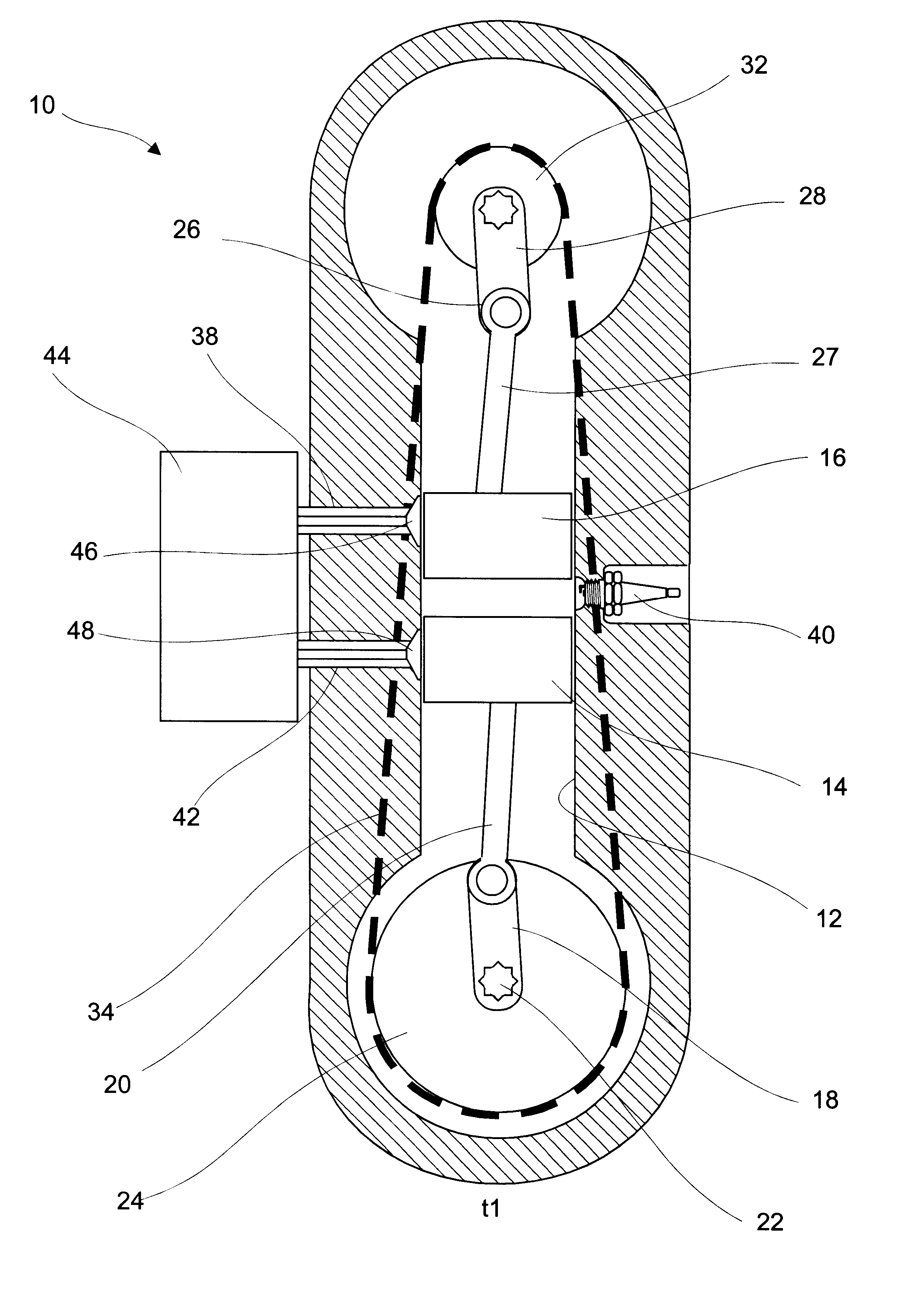
Referring now to the drawings, the present invention is represented by the numeral 10. The invention may also be referred to herein after as "improvements" 10 of the internal combustion engine having variable compression and asymmetrical stroke.

The following description in conjunction with viewing the drawings will aid in understanding the present invention. The structure and operation are as follows.

The improvements 10 include a cylinder 12, drive piston 14, auxiliary piston 16, drive crank 22, drive gear 24, auxiliary crank 26, auxiliary gear 32, timing chain 34, intake port 38, ignition device 40, and exhaust port 42. An automated controller 44 is also provided.

It is contemplated that as opposed to the timing chain 34 described herein, a plurality of interconnecting helical gears 31 can be employed to carry out the intended purposes of the timing chain 34. The gears 31 can be manually or automatically adjusted to affect phase shift of the pistons 14 an 16.

The pistons 14 and 16 ar...


PUM


Abstract

A variable compression and asymmetrical stroke internal combustion engine includes a cylinder, a drive piston reciprocally disposed in the cylinder, an auxiliary piston reciprocally disposed in the cylinder, apparatus for reciprocating the auxiliary piston at twice the speed of the drive piston and in a manner wherein the relative reciprocation is asymmetrical, an intake port communicably connected to the cylinder, an exhaust port communicably connected to the cylinder, and an ignition device operably connected to the cylinder.

Description

BACKGROUND OF INVENTION1. Field of the InventionThis invention relates to internal combustion engines, and more particularly to an improvement in engines of the type employing main and auxiliary pistons.2. Prior ArtThe internal combustion engine of the present invention differs in significant regard from prior conventional internal combustion engines of the two stroke cycle and four stroke cycle types. However, certain terminology developed with reference to such previously known engines is of value in clarifying the operation of the engine of this invention.The quasi harmonic motion of a piston operatively connected to a crankshaft has given rise to such terminology as "top dead center" (TDC) and "bottom dead center" (BDC) positions of a piston. Top dead center position refers to a position of the piston, connecting rod and crankshaft in which the axis of rotation of the crankshaft and the axis of pivotal connection of the connecting rod with the piston and the crankshaft are align...

Claims


Application Information

Patent Timeline
IPC IPC(8): F02B41/00F02B75/00F02B75/04F02B75/28
CPCF02B41/00F02B75/04F02B75/28F02B75/042
Inventor ACHTERBERG, RAYMOND C.
Owner ACHTERBERG RAYMOND C
Why Eureka
Try Eureka