Sheet post-processing apparatus

a post-processing and sheet technology, applied in the field of sheet post-processing, can solve the problems of large driving force, complex structure, and uniform sheet size of the apparatus used for the apparatus

Inactive Publication Date: 2001-05-15
SINDOH
View PDF13 Cites 178 Cited by
  • Summary
  • Abstract
  • Description
  • Claims
  • Application Information

AI Technical Summary

Problems solved by technology

However, since the conventional sheet post-processing apparatus aligns a side of each of the sheets accommodated into the aligning tray by the solenoid, there is a problem that sizes of the sheets used for the apparatus should be uniform.
Further, when a plurality of sheets are accommodated into the accommodation tray, since a large of load is applied to

Method used


Image

  • Sheet post-processing apparatus
  • Sheet post-processing apparatus
  • Sheet post-processing apparatus

Examples


Embodiment Construction

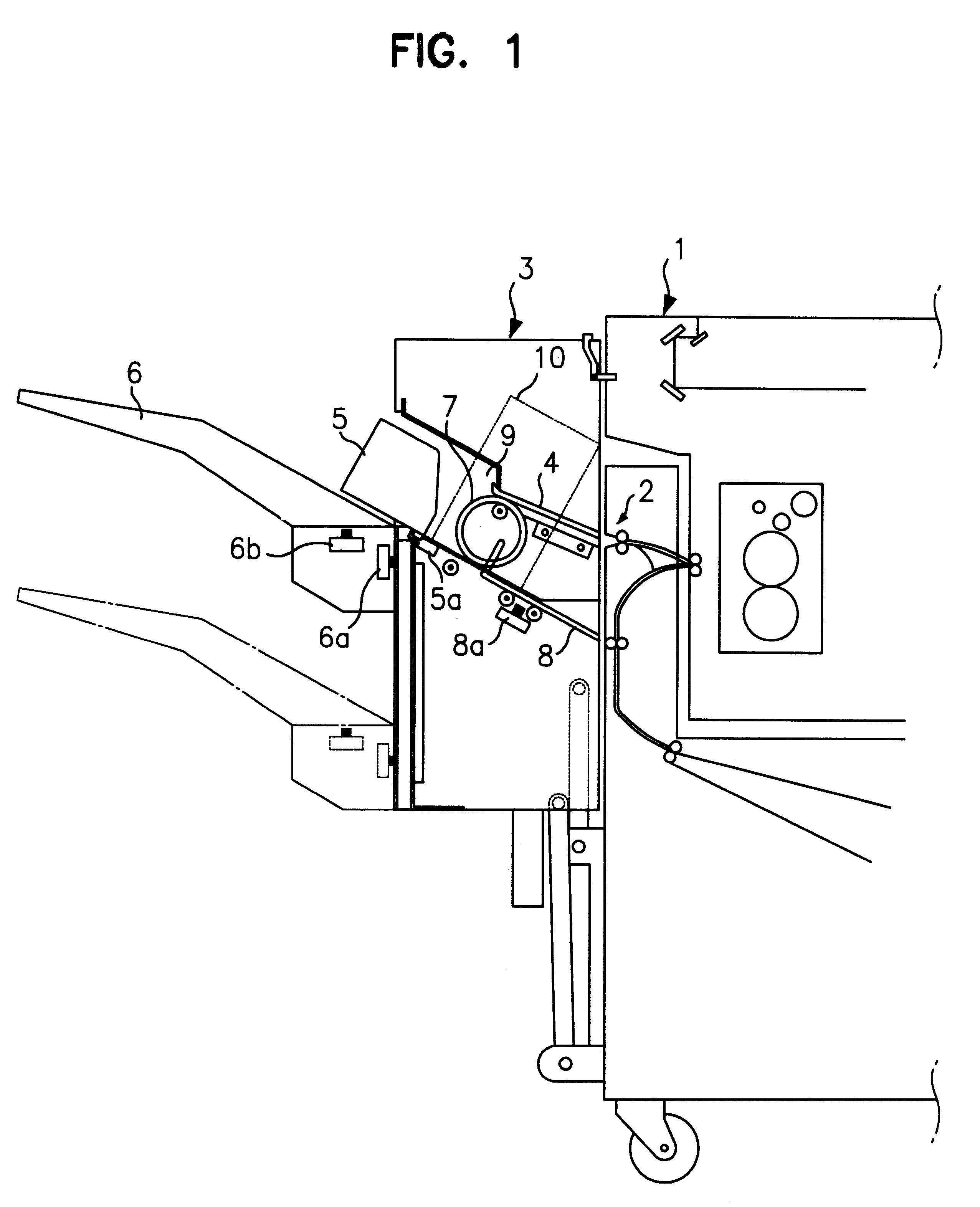
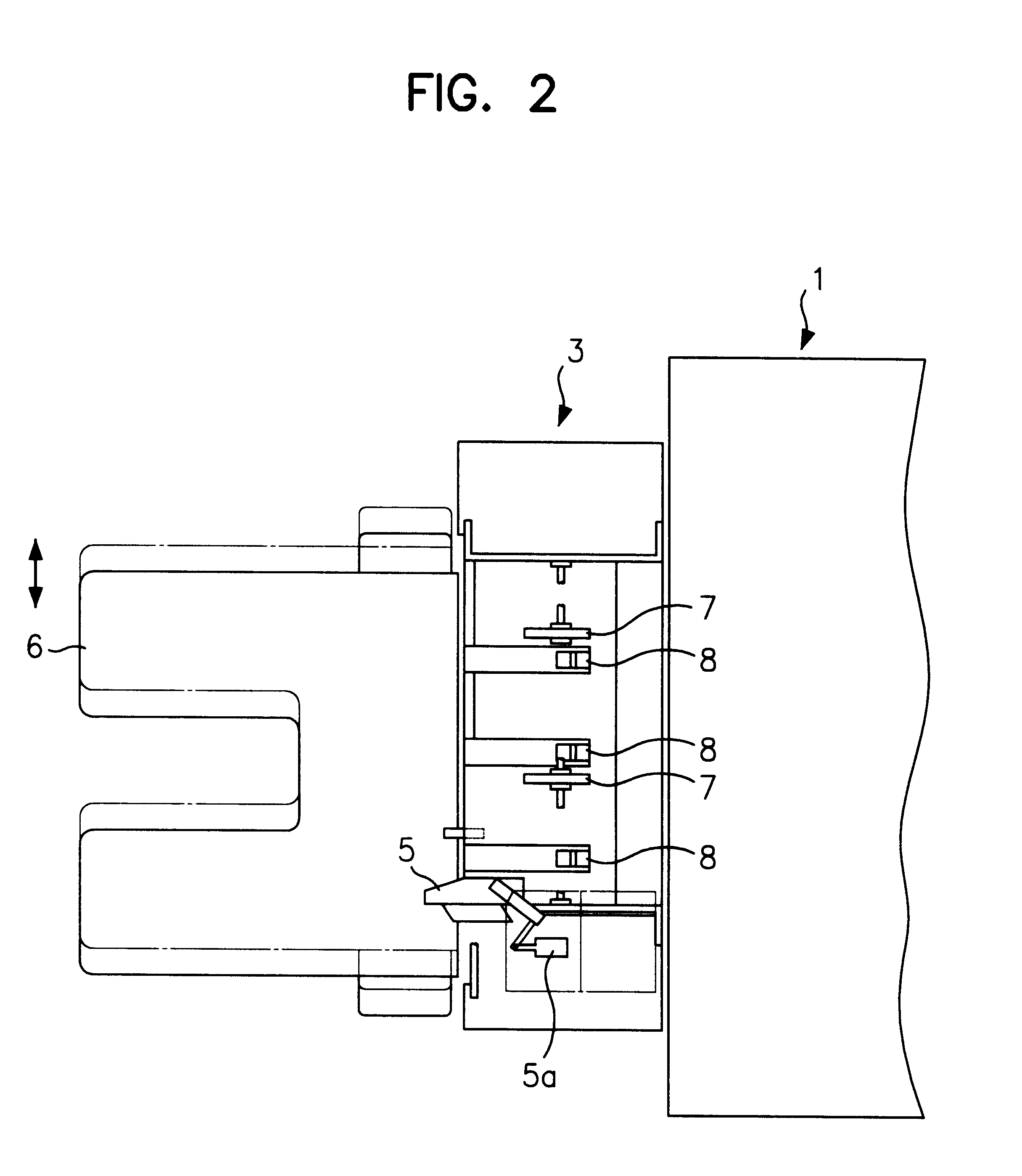
Hereinafter, the embodiment according to the present invention will be described in detail, referring to the accompanying FIGS. 3 to 13.

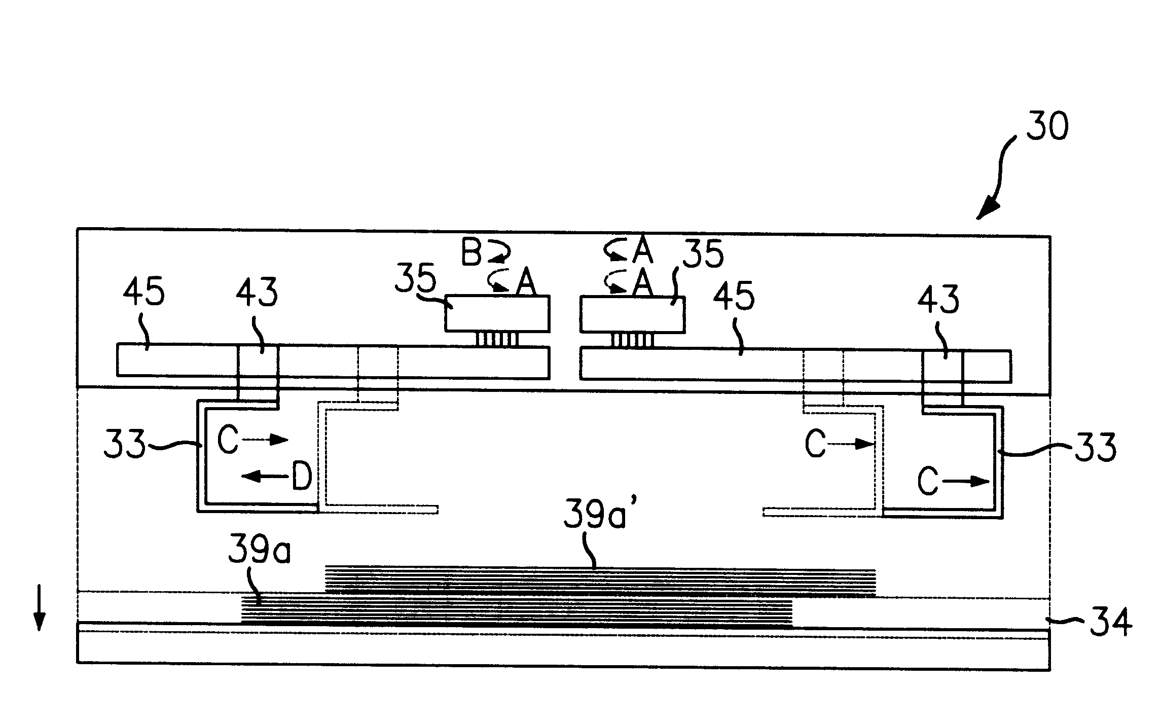
FIG. 3 is a side view showing a structure of a sheet post-processing apparatus according to the present invention, FIG. 4 is a perspective view showing a disassembly of an upper tray driving portion of the sheet post-processing apparatus, FIG. 5 is a perspective view showing a disassembly of an abutment of the sheet post-processing apparatus, FIG. 6 is a cross-sectional view showing an assembly of the FIG. 5, FIG. 7 is a perspective view showing a disassembly of another embodiment of an abutment the sheet post-processing apparatus, and FIG. 8 is a cross-sectional view showing an assembly of the FIG. 7.

In FIGS. 3 to 13, the reference numerals are as follows: 30 indicates sheet post-processing apparatus, 31 conveyer, 32 sheet outlet, 33 upper tray, 33a first erect portions, 33b second erect portion, 33c through hole, 34 lower tray, 35 upper motors, 36...


PUM

PropertyMeasurementUnit
Forceaaaaaaaaaa
Diameteraaaaaaaaaa
Sizeaaaaaaaaaa

Abstract

A sheet post-processing apparatus comprises a conveyer for conveying the sheets discharged from the image forming system; a conveying device for conveying the sheets discharged from the image forming system; a pair of upper trays for accommodating the sheets conveyed by the conveying devices, and being horizontally moved in order to align the sheets accommodated therein and fall down the aligned sheets; a pair of upper tray driving devices for providing a driving force to the upper trays; a transmission unit for transmitting the driving force of the upper tray driving device to the upper trays; a lower tray for loading the sheets fallen from the upper trays; and a lower tray driving device for moving the lower tray in upper and lower directions in order to retain distance between the upper trays and the lower tray within a predetermined range. Thus, the sheet post-processing apparatus can accommodate variant size sheets by mechanism consisting of simple and cheap elements.

Description

1. Field of the InventionThe present invention relates to a sheet post-processing apparautus adjacent to a sheet discharging section of an image forming system such as a copier, a printer, a facsimile and so on. More particularly, it relates to a sheet post-processing apparatus capable of performing post-process such as a stapling or a punching to sheets on which images are formed by the image forming system.2. Description of Related ArtRecently, the image forming system is developed from analogue type into digital type. The digital image forming appartus can perform one or more function(s) of copy function, print function, facsimile function and selectively discharge the sheets on which images are formed.That is, since the digital image forming system can store image data to be copied or printed, the image forming system can print the images on the sheets and discharge the sheets on which the images are formed, according to sequency which user wants. Therefore, a sheet post-process...

Claims


Application Information

Patent Timeline
IPC IPC(8): B42C1/12B65H33/08B65H33/00B65H31/20B65H31/32B65H31/30B65H33/06
CPCB42C1/12B65H31/20B65H31/3009B65H33/08B65H2301/42192B65H2301/42261B65H2405/351B65H2408/121B65H2801/27B65H31/02B65H31/10B65H31/3018B65H2301/4212B65H2301/4213B65H2405/11151B65H2801/06B65H31/30
Inventor CHUNG, JAE-HEON
Owner SINDOH
Why Eureka
Try Eureka