Transport band for conveying along a spiral path

a technology of conveyor belts and spiral paths, applied in the direction of conveyor belts, transportation and packaging, rolling carriages, etc., can solve the problems of known conveyor belts that require tools, certain food products have a tendency to freeze fast on the conveyor belts, and food product remains are l

Inactive Publication Date: 2001-05-29
UNI CHAINS INT +1
View PDF16 Cites 97 Cited by
  • Summary
  • Abstract
  • Description
  • Claims
  • Application Information

AI Technical Summary

Problems solved by technology

Firstly, certain food products have a tendency to freeze fast on the metal belts, even though these have wire- or net-formed supporting surfaces.
Thereby food-product remains are left on the belt after the thermal treatment, which is undesirable not only from the point of view of hygiene but also because it necessitates an increase in the efforts required for cleaning.
Another great disadvantage is that the known belts require to

Method used


Image

  • Transport band for conveying along a spiral path
  • Transport band for conveying along a spiral path
  • Transport band for conveying along a spiral path

Examples


first embodiment

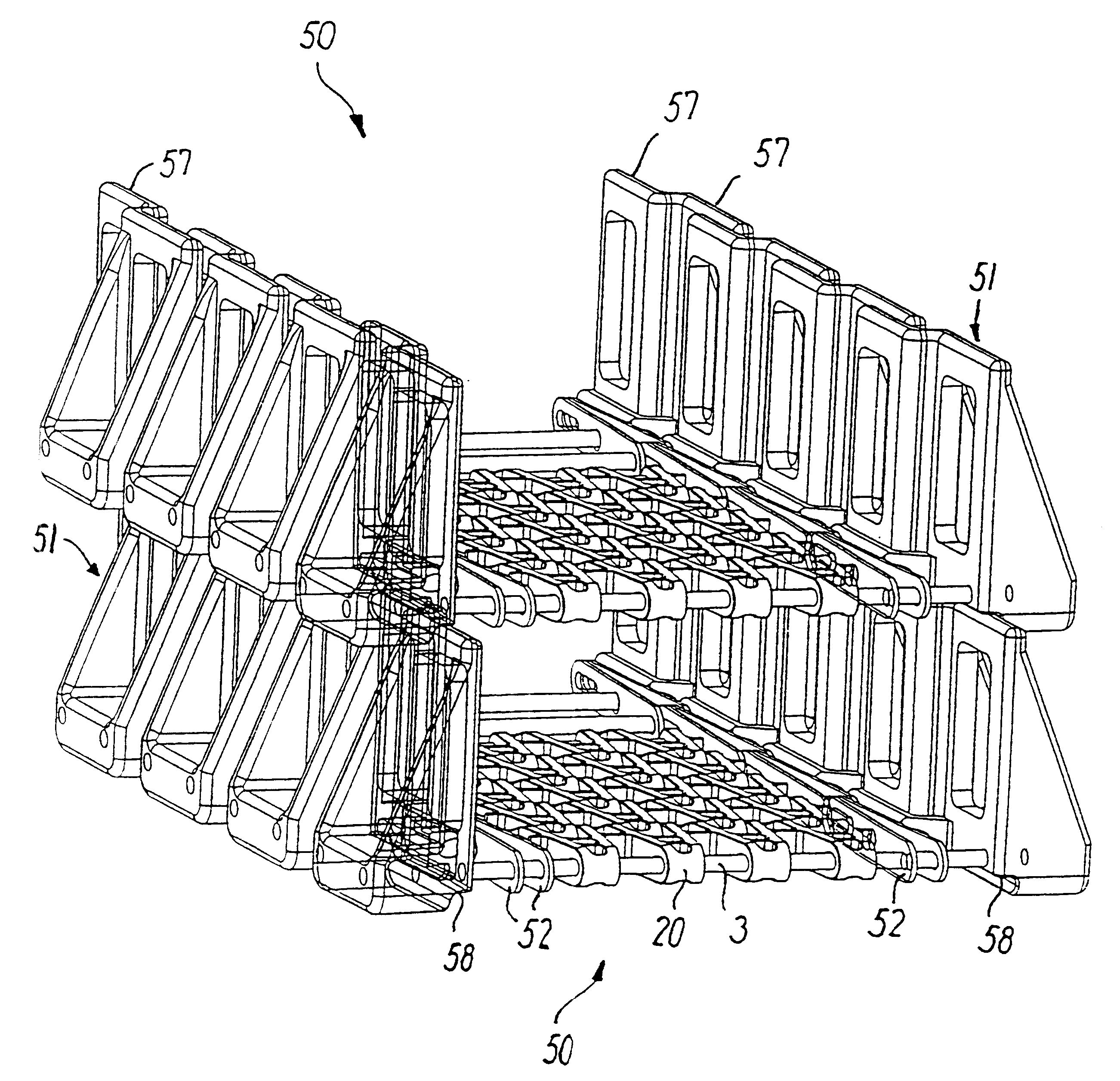
In FIGS. 19-21 is shown a large outer link 71 moulded in plastic or steel as a one-piece unit. The selection of construction material will depend on the degree of strength it is desired to achieve. The underside has a track 58, the breadth of which corresponds to the total breadth of the top edge 57, in that the link comprises two offset but integrally-formed, vertically-extending areas or wall parts 54, and inclined reinforcement areas 62 integral herewith and down to a part 69 in which the holes 55 are provided for the fastening of the axles 3. The track 58 arises between downwardly-extending parts 59 and 60 in such a manner that the conveyor belt cannot only rest on top of corresponding outer links, but also so that these are guided in the lateral direction. As shown in FIGS. 19-21, the outer link 71 can also comprise a central and horizontally-extending centre rib 53 for engagement with a corresponding recess 63 in an adjacent link. There is hereby formed a railing which faces i...

second embodiment

FIG. 22 shows a large outer link, i.e. where the walls 54 are configured with large openings 64 for the introduction of air or other gases, e.g. for cooling or heating of items on the conveyor belt.

Finally, in FIGS. 23-24 is seen an embodiment where the downwardly-extending part 69, the underside of which is arranged e.g. to rest against a helical stack's support, has a moulded-in steel item 67, e.g. of stainless steel. The steel item 67, e.g. having a shape as shown in the drawing before being moulded-in, can be moulded-in at the same time that the link 71 itself is moulded. It is hereby achieved that the outer links 71 do not get into direct contact with possible supporting elements, which are usually of stainless steel. The contact between the lowermost tier in a helical stack and its support thus takes place solely via the downwardly-facing surfaces 68, so that the plastic links 71 do not make contact with the helical stack's support, which often comprises an endless conveyor ch...


PUM


Abstract

A conveyor belt (1) is composed of a number of identical links in the formation of an endless belt, where each link comprises at least one axle (3) arranged transversely in relation to the direction of travel (2), and an outer link (4) at each side in engagement with the axle. Each outer link comprises an elongated hole for the adjacent link's axle, so that the belt can be driven in a curve in the plane of the belt. Each outer link has at least one securing hole for a transverse axle, where the coupling-together between the axle (3 and the outer link (4) is effected by a separable snap-lock. The outer link is moulded as a one-piece unit in a suitable plastic material, preferably by injection moulding. The outer links (4) can also be configured in a larger version for the construction of conveyor belts for operation in self-stacking helical systems.

Description

PRIOR ART TECHNIQUEThe invention concerns a conveyor belt of the kind disclosed in the preamble to claim 1. Such conveyor belts arranged for the transport of items, e.g. food products, canned goods and the like, are known from EP patent application No. 0283209 (Ashworth Bros. Inc., US) or EP patent No. 0288475 (Frigoscandia Food Process Systems Aktiebolag, SE), where the latter publication discloses a conveyor belt arranged especially for operation in connection with helical plants for cold storages for the freezing of newly-produced food products or portions of food products.All of the parts in the known conveyor belts are normally made of steel and are assembled by welding of the individual parts in the formation of a chain link, where the outer links are so strong that they can support the overlying parts of the belt when operating in a helical plant.The known constructions have several disadvantages. Firstly, certain food products have a tendency to freeze fast on the metal belt...

Claims


Application Information

Patent Timeline
IPC IPC(8): B65G21/18B65G17/06B65G21/00B65G17/00
CPCB65G17/064B65G21/18B65G2201/02B65G2207/24
Inventor DAMKJAER, POUL ERIKRAUM, JACK RONALDSMITH, ANDREW CLYDE
Owner UNI CHAINS INT
Why Eureka
Try Eureka