Internal voltage fall-down circuit

a voltage drop and circuit technology, applied in process and machine control, semiconductor devices, instruments, etc., can solve the problems of preset voltage change, fluctuation of internal supply voltage levels,

Inactive Publication Date: 2001-05-29
HYUNDAI ELECTRONICS IND CO LTD
View PDF9 Cites 29 Cited by
  • Summary
  • Abstract
  • Description
  • Claims
  • Application Information

AI Technical Summary

Problems solved by technology

Normally, in the above-mentioned internal voltage fall-down circuit, variations in processes or noises occurring during operation of the on-chip circuit may cause the internal supply voltage levels to fluctuate.
The noises occurring during operation of the on-chip circuit mean current spikes which cause a large current flow at a sensing or an input / output circuit, noise of which affects the internal circuit to cause change of preset voltage (i.e., change in potentials of the reference voltage).

Method used


Image

  • Internal voltage fall-down circuit
  • Internal voltage fall-down circuit
  • Internal voltage fall-down circuit

Examples


Embodiment Construction

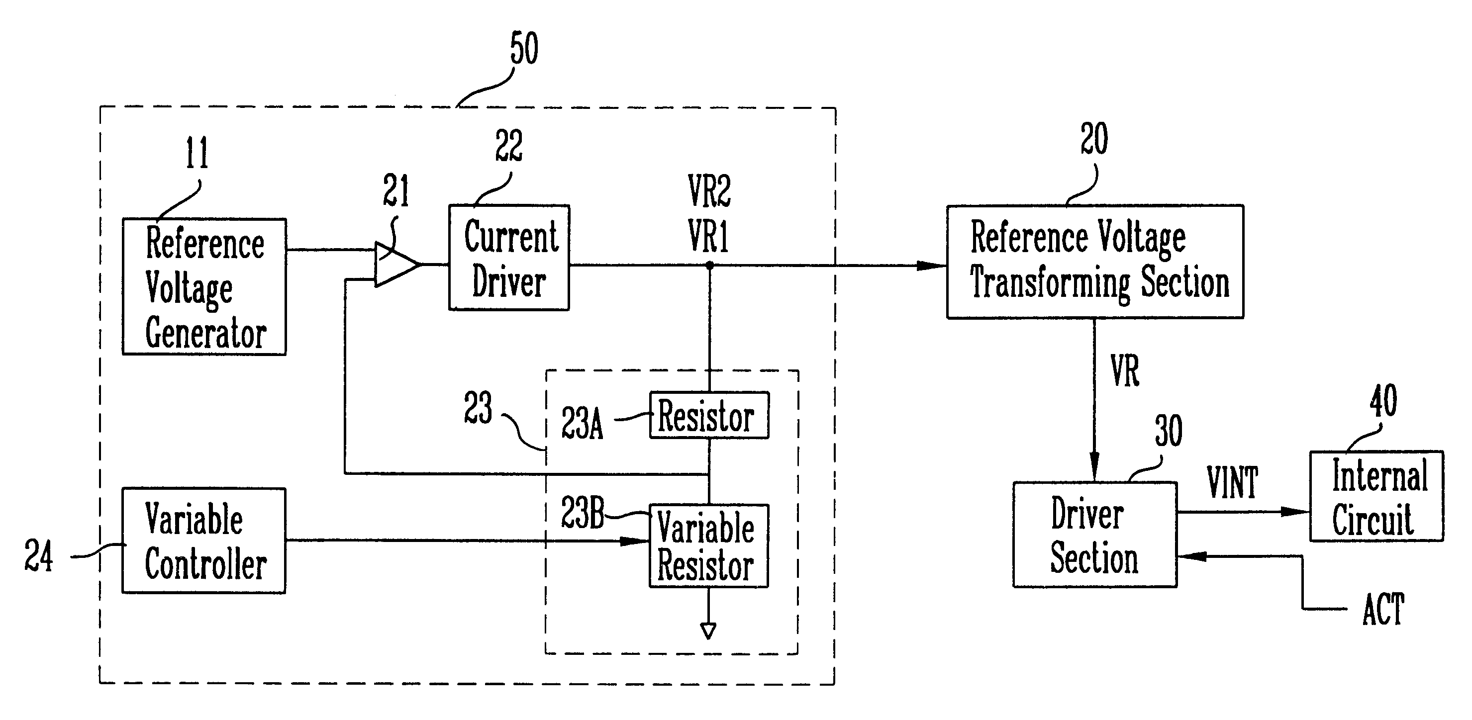
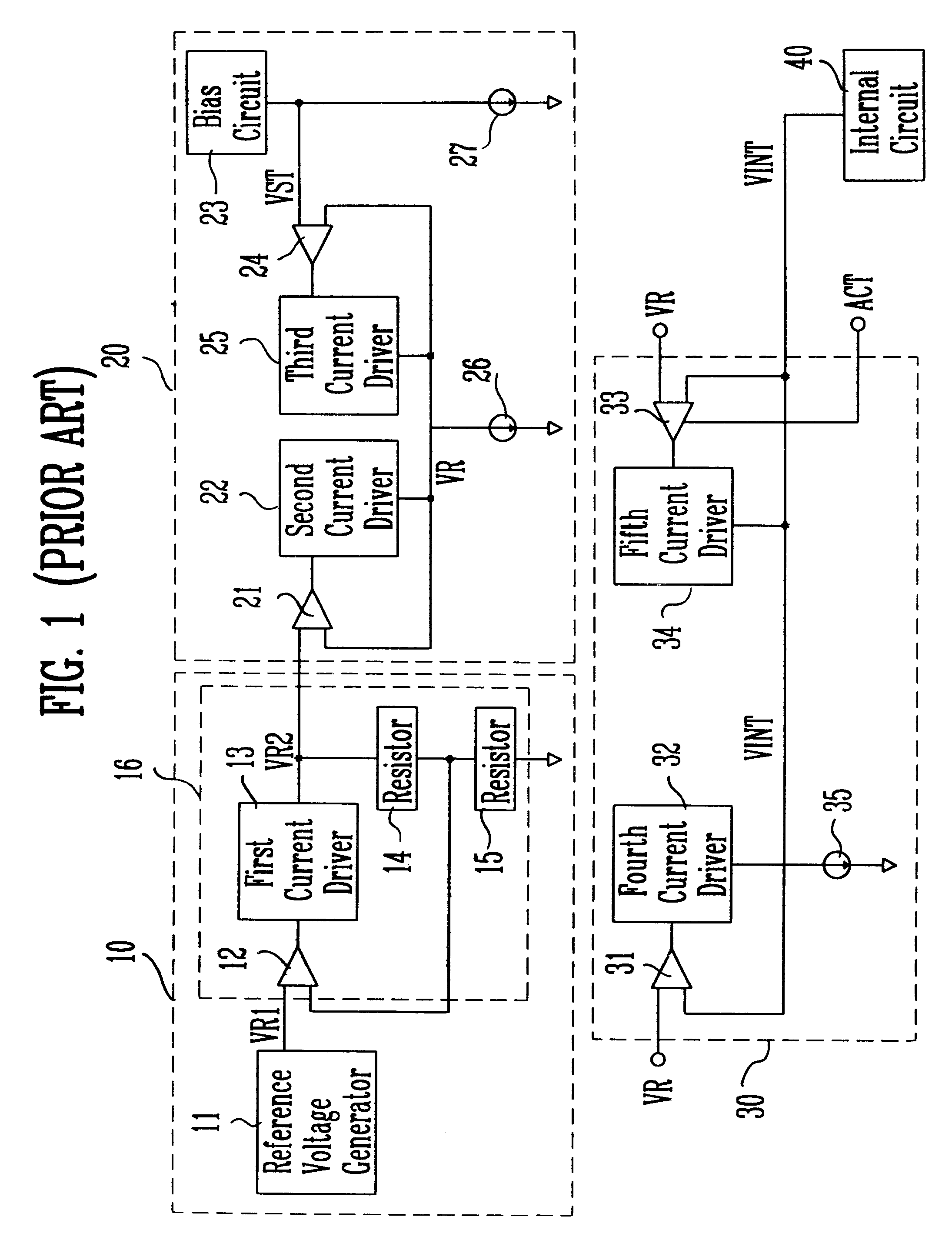
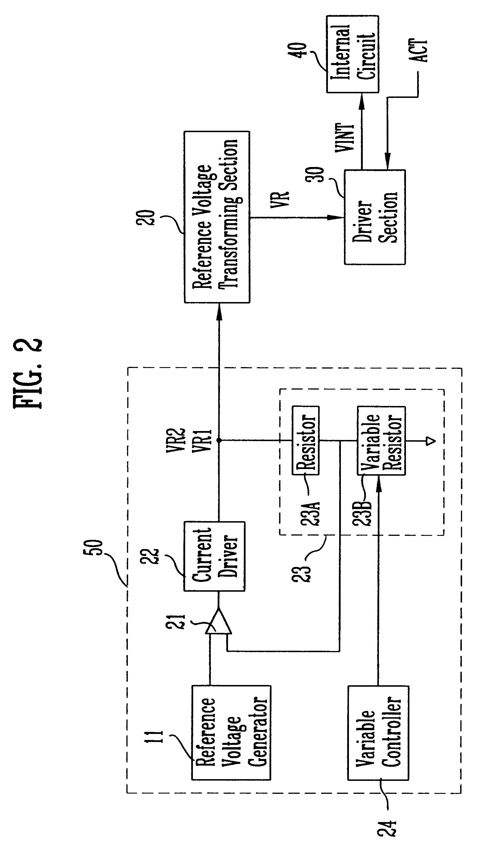
FIG. 2 is a block diagram for illustrating the internal voltage fall-down circuit according to one embodiment of the present invention, in which the same components to those described with respect to FIG. 1 will be designated to same reference numerals.

The internal voltage fall-down circuit according to one embodiment of the present invention includes a reference voltage generating section 50 for variably generating an optimum reference voltage, the level of which is compensated for depending on changes in the preset reference voltage VR2 before fuse blowing; a reference voltage transforming section 20 for receiving the reference voltage VR2 from the reference voltage generating section 50, transforming the reference voltage VR2 into voltage for a normal mode when the operation mode internally set is set to the normal mode, and transforming the reference voltage VR2 into voltage for a stress mode when it is set to the stress mode; and a driver section 30 for providing the signal fro...


PUM


Abstract

An internal voltage fall-down circuit includes a reference voltage generating section for variably generating an optimum reference voltage level of which is compensated for depending on changes in the present reference voltage before fuse blowing, a reference voltage transforming section for receiving the reference voltage from the reference voltage generating section and then transforming the reference voltage into voltage for a normal mode or a stress mode which are presently set, and a driver section for providing a signal from the reference voltage transforming section to an internal circuit as an internal supply voltage.

Description

1. Field of the InventionThe present invention relates to an internal voltage fall-down circuit of a semiconductor device. In particular, the present invention relates to an internal voltage fall-down circuit which can test fuse programs for controlling an internal power supply voltage by pad signals without fuse blowing.2. Description of the Prior ArtA conventional internal voltage fall-down circuit includes a reference voltage generating section 10, a reference voltage transforming section 20 and a driver section 30, as shown in FIG. 1, wherein an output signal Vint from the conventional internal voltage fall-down circuit is input to an internal circuit 40 as supply voltage. An output signal VR2 from the reference voltage generating section 10 is input to a first input terminal of a first comparator 21 in the reference voltage transforming section 20, and an output signal VR from the reference voltage transforming section 20 is used as a final comparison voltage of the driver sect...

Claims


Application Information

Patent Timeline
Patent Type & Authority Patents(United States)
IPC IPC(8): G05F1/46G05F1/10H01L27/04
CPCG05F1/465H01L27/04
Inventor OH, YOUNG NAMLEE, JUNG SEOP
Owner HYUNDAI ELECTRONICS IND CO LTD
Why Eureka
Try Eureka