
ATM switching architecture for a wireless telecommunications network

switching architecture technology, applied in the field of atm switching architecture for a wireless telecommunications network, can solve problems such as slow hand-o

Inactive Publication Date: 2001-05-29
NEC CORP
View PDF8 Cites 95 Cited by
  • Summary
  • Abstract
  • Description
  • Claims
  • Application Information

AI Technical Summary

Benefits of technology

The problem of having to do a CAC (connection admission control) recalculation for each individual VC (in order to assure that the new port has sufficient bandwidth to accept the VCs) can be avoided.
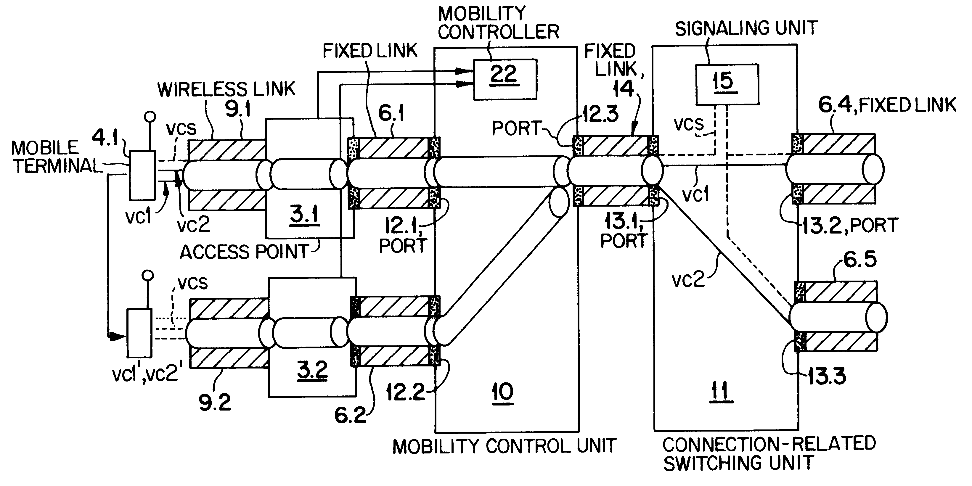
The two units may be realized within the same hardware but in separate functional units (a hybrid VP / VC switch). The control program defines whether the unit is for mobility control or for VC switching. This minimizes the costs of the hardware. It is not necessary to develop and to produce different components. The two units of the hardware component are connected in series by means of a fixed (external or internal) loopback link. One particular port of the mobility control unit is therefore connected with one particular port of the connection related switching unit.
There may be two physically separate dedicated hardware components. It is an advantage of the present ATM switch architecture that it can be used to modify (i.e. extend the operation of) existing ATM switches by simply inserting a front-end module between the access points (that serve for wireless communication links) and the conventional ATM-switch.
The intra-switch handover is very simple. If the existing radio link between the access point and the mobile terminal undergoes degradation or breaks down, the mobility control unit selects the new access point (which may be determined either by the mobile terminal or by the mobility control) and reassigns the Virtual Path Identifier (VPI) to the corresponding new port. All VCs are therefore shifted to the new port by one operation.

Problems solved by technology

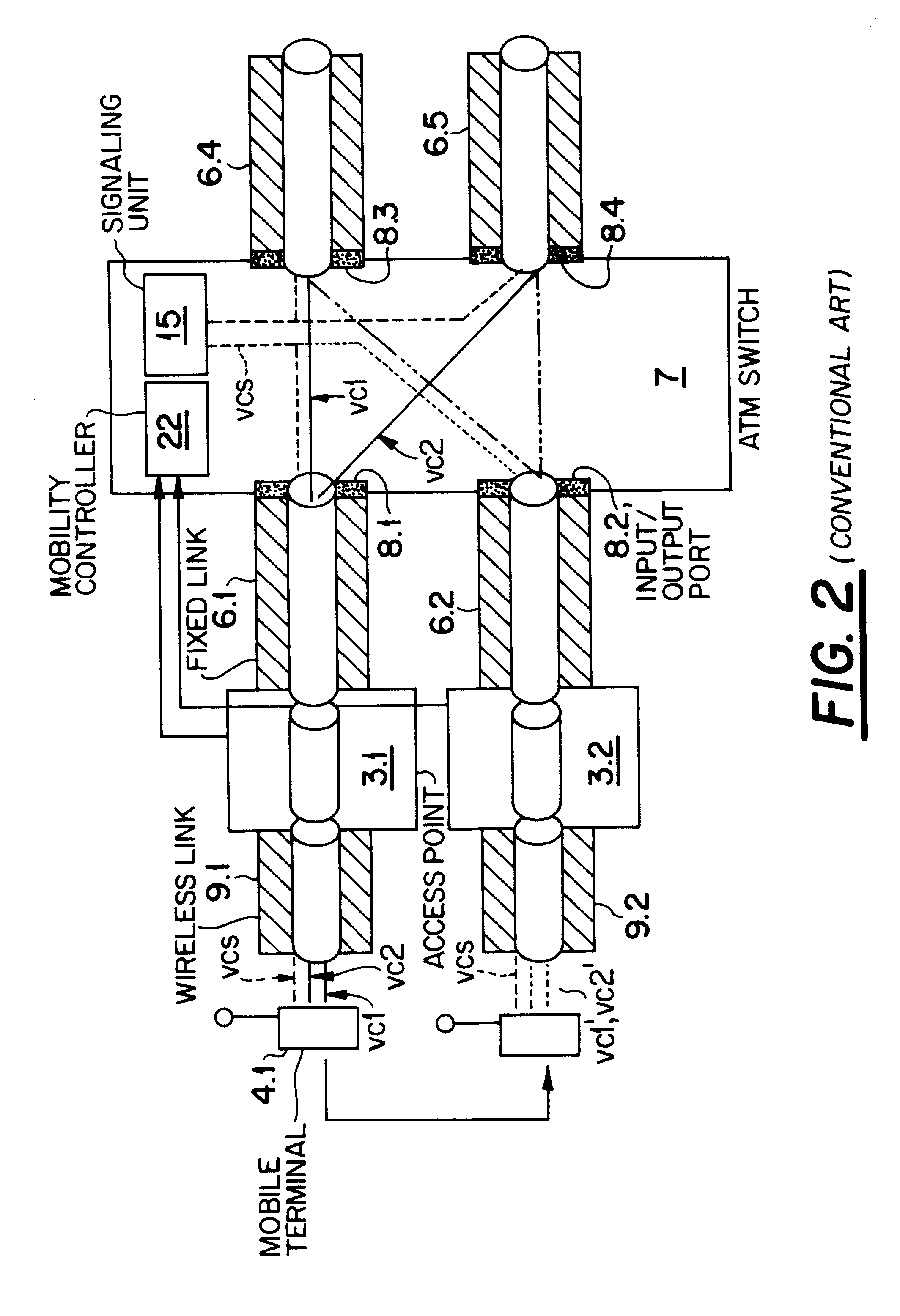
However, if there is no pre-established VP / VC, the hand-off is slow.
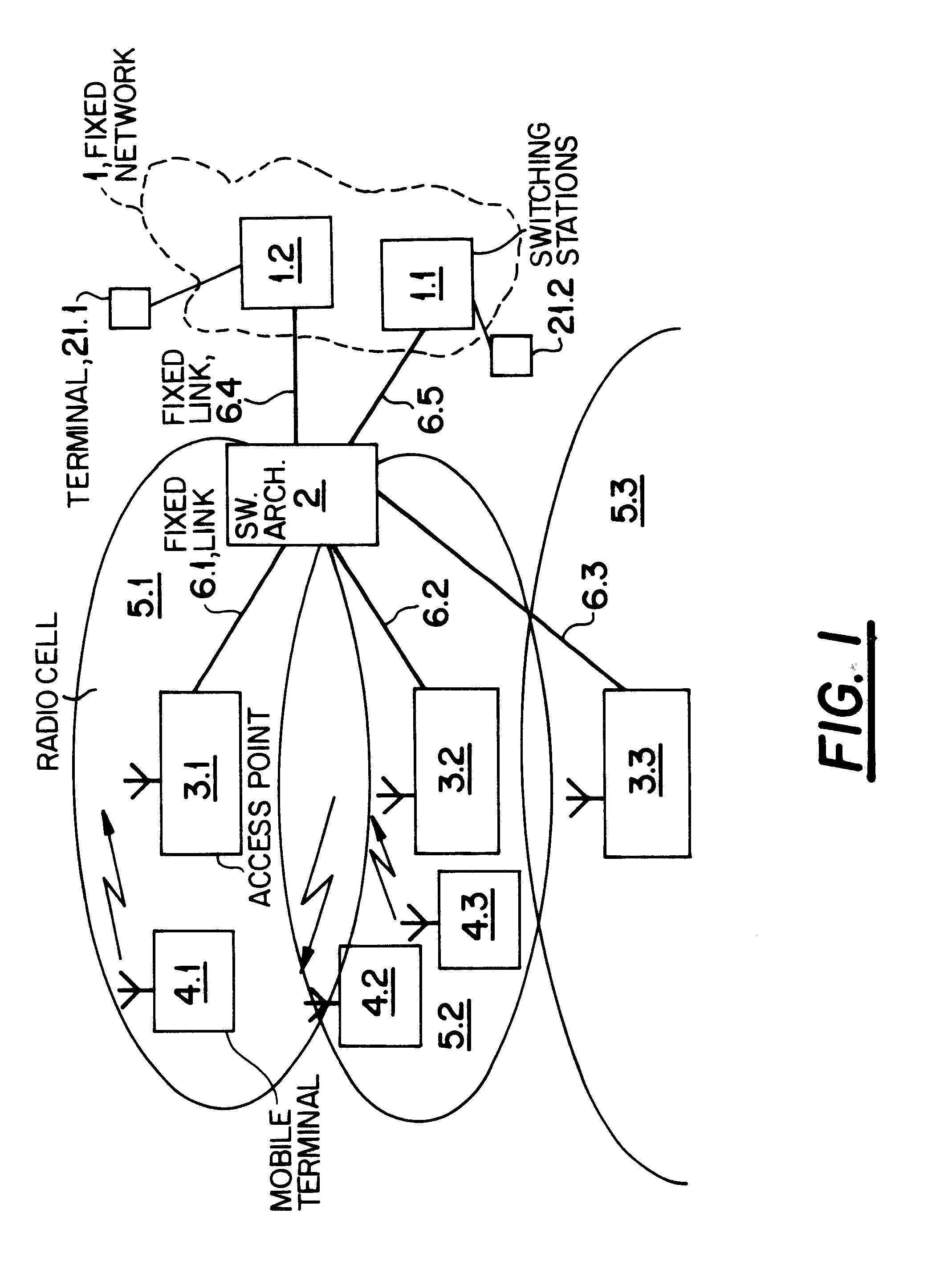
However, a cellular communications network has to deal with handovers and therefore with switching between several physical ports.

Method used


Image

  • ATM switching architecture for a wireless telecommunications network
  • ATM switching architecture for a wireless telecommunications network
  • ATM switching architecture for a wireless telecommunications network

Examples


first embodiment

This first embodiment which uses a separate VP switch for mobility operation works as follows:

After association of the mobile terminal 4.1 with the access point 3.1 a VP from unit 11 via unit 10 and the access point 3.1 to the mobile terminal 4.1 is created. At the air interface, the VP is mapped into one or several radio channels. One or multiple signaling VCs between the mobile terminal 4.1 and the signaling unit 15 of unit 11 are automatically configured. Other steps like authentication of the mobile terminal, address registration, verification can take place by using these established signaling VCs. De-registration results in the reverse steps of registration.

According to the invention, the mobility control unit 10 is not involved in the handling of the data transmitted in the signaling channel. All VCs pass the first unit 10 in one VP.

Connection setup results in the creation of a VC between the mobile terminal 4.1 and the switching unit 11. The VC is inside the VP that is assoc...


PUM


Abstract

An ATM switching architecture for a wireless telecommunications network includes two separate units having different functionality. The first unit performs mobility control, wherein a virtual path which contains all virtual channels of a mobile terminal is switched from a first port associated with a first access point, to a second port connected to a first port of the second unit. The second unit performs a switching operation, wherein the virtual channels of the mobile terminal are distributed from the first port of the second unit to different destination ports of the second unit. In one embodiment, the two units may be dedicated hardware components, and in another embodiment, one single hardware component is functionally separated into two separate units connected by a loopback link.

Description

The invention relates to an ATM switching architecture for a wireless telecommunications network, comprising a plurality of ports for a plurality of access points of a wireless cellular communication system and means for performing switching operations and mobility control.PRIOR ARTIn order to provide mobile communication services, modern telecommunications networks include switching stations (switching centers) each handling a plurality of access points (base stations) for establishing radio links to mobile terminals. One single switching station not only establishes the connection between the mobile terminal and any requested other terminal in the network, but it also deals with the mobility control for the mobile terminal. This control manages the handover if the radio link deteriorates during the ongoing connection and if a new radio link has to be established. The new radio link may be established to the access point of a neighbouring cell or to that one in the same cell.There ...

Claims


Application Information

Patent Timeline
IPC IPC(8): H04L12/56H04Q7/24H04Q7/38H04L49/111H04W36/08H04W76/04
CPCH04L49/105H04L49/20H04L49/254H04L49/30H04L49/3063H04L49/552H04L2012/5607H04L2012/5619H04W36/00
Inventor KUHNEL, THOMASVARLESE, CHRISTOPHER
Owner NEC CORP
Learn More