Air deflector for motor vehicles
a technology for air deflectors and motor vehicles, which is applied to roofs, heating types, doors, etc., can solve the problems of air deflectors used, the device is not generally structured as a universal, and the surface is difficult to keep clean for viewing and other purposes, so as to achieve efficient and effective air flow cleansing of the posterior area
- Summary
- Abstract
- Description
- Claims
- Application Information
AI Technical Summary
Benefits of technology
Problems solved by technology
Method used
Image

Examples
Embodiment Construction
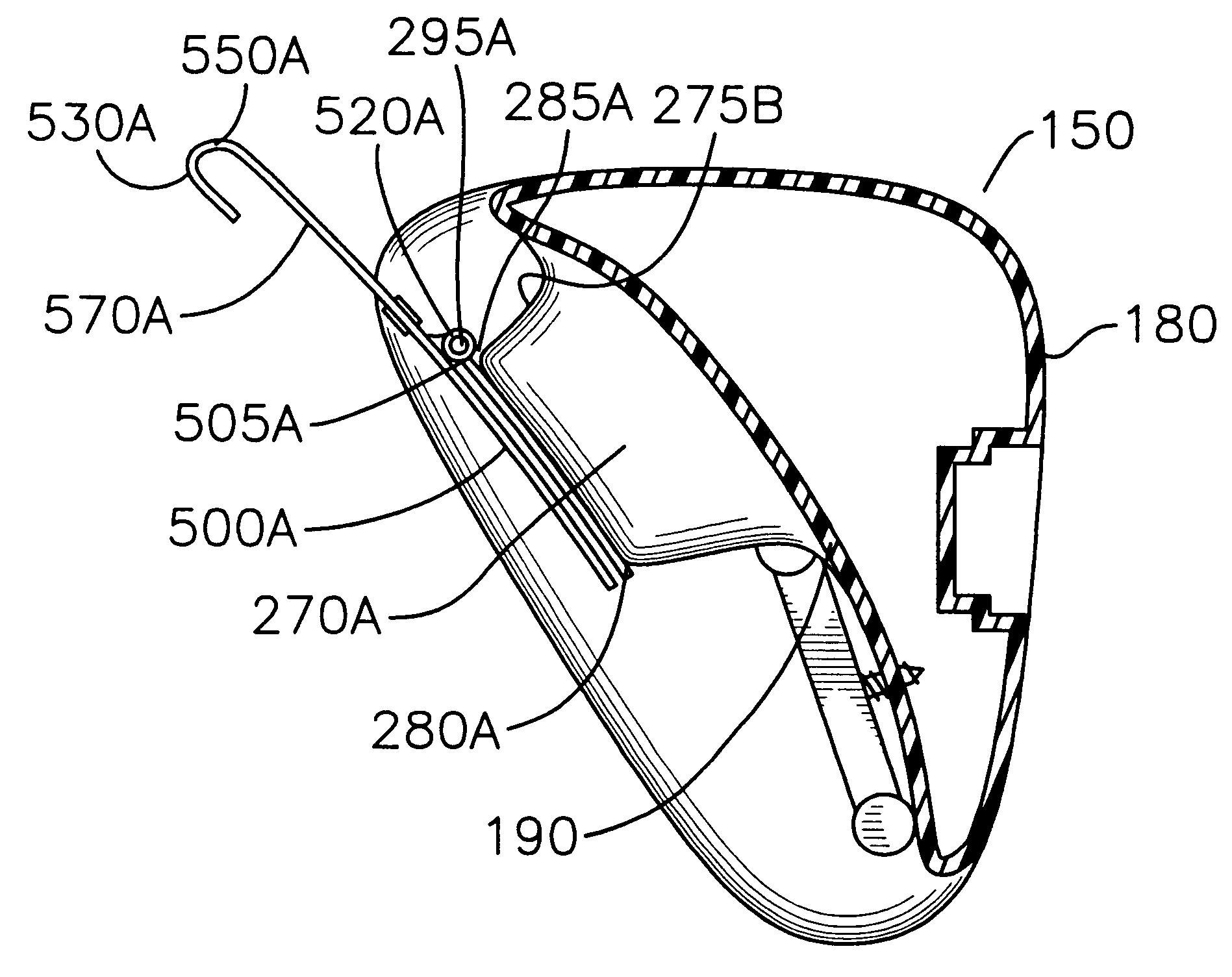
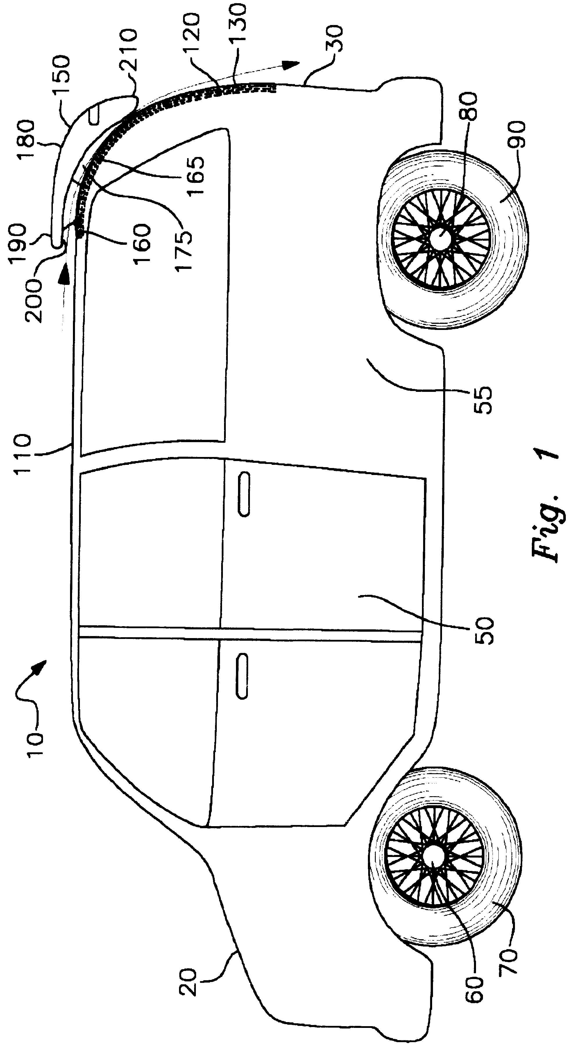
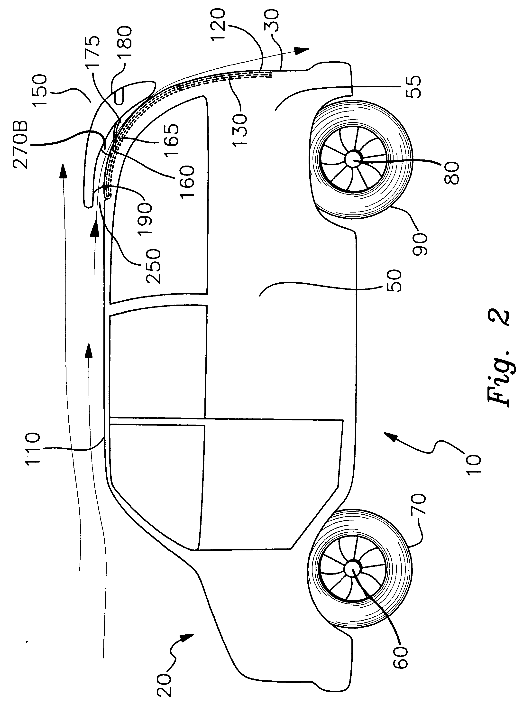
The subject invention is an air deflector for a motor vehicle that is adapted to be attached to the posterior portion of a roof structure of a motor vehicle with some limited overhang over the rear vehicle surface for purposes of directing the flow of air that accumulates over the roof of a moving motor vehicle so as to move such air downwardly over rear surface of the motor vehicle, said deflector comprising an air deflector member forming with the motor vehicle an internal air passage that is curved downwardly towards the rear vehicle surface from the upper rear surface of the roof in order to deflect air movements from a horizontal flow pattern over the roof surface to a substantially vertical flow directed downwardly and adjacent to the posterior surface of the vehicle, such air deflector device having a concave lower surface adapted to fit conformingly over the rear portion of the roof and adjacent upper portion of the rear surface of the vehicle, with specialized attachment me...
PUM
 Abstract
Description
Claims
Application Information
 - R&D
- Intellectual Property
- Life Sciences
- Materials
- Tech Scout
- Unparalleled Data Quality
- Higher Quality Content
- 60% Fewer Hallucinations
Browse by: Latest US Patents, China's latest patents, Technical Efficacy Thesaurus, Application Domain, Technology Topic, Popular Technical Reports.
© 2025 PatSnap. All rights reserved.Legal|Privacy policy|Modern Slavery Act Transparency Statement|Sitemap|About US| Contact US: help@patsnap.com