Weir box for drilling mud separation unit

Inactive Publication Date: 2001-06-12
WILLIAMS J TERRELL
View PDF9 Cites 39 Cited by
  • Summary
  • Abstract
  • Description
  • Claims
  • Application Information

AI Technical Summary

Problems solved by technology

The mechanical shale shaker screens are limited to short life, and the screens become coated with sticky clays closing the pores or mesh openings resulting in fluid or mud loss.
This adds to the problem as addition

Method used


Image

  • Weir box for drilling mud separation unit
  • Weir box for drilling mud separation unit
  • Weir box for drilling mud separation unit

Examples


Embodiment Construction

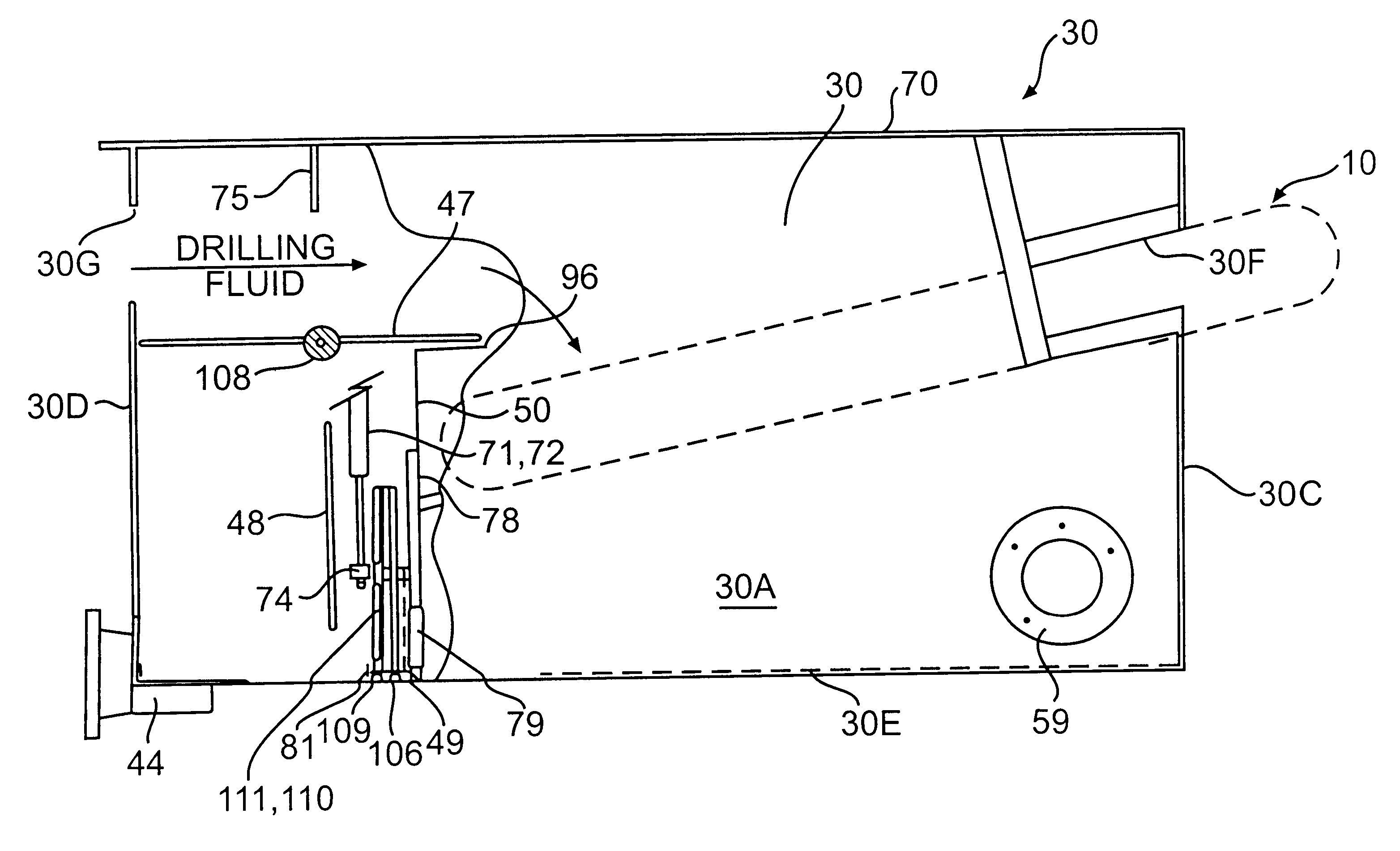
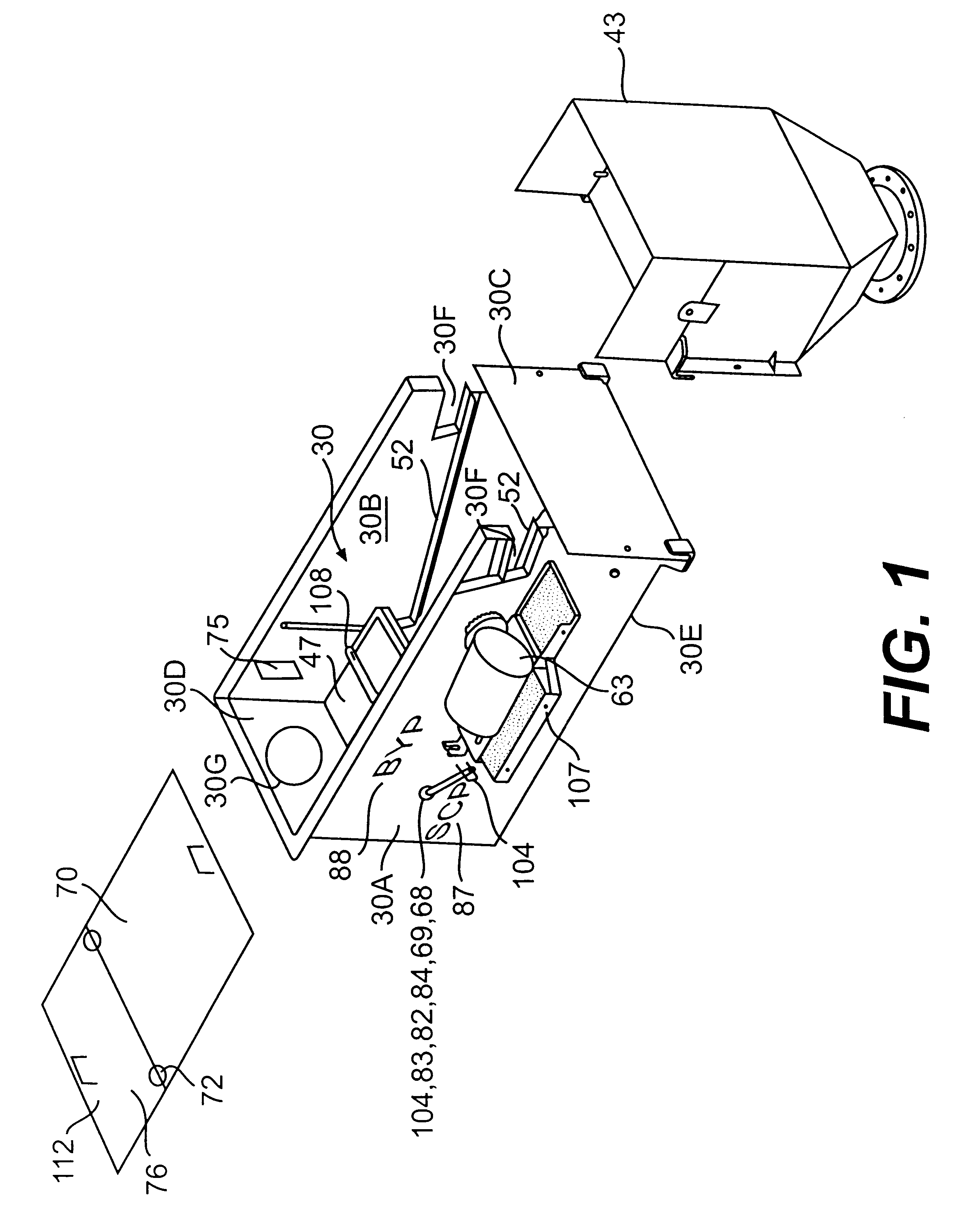
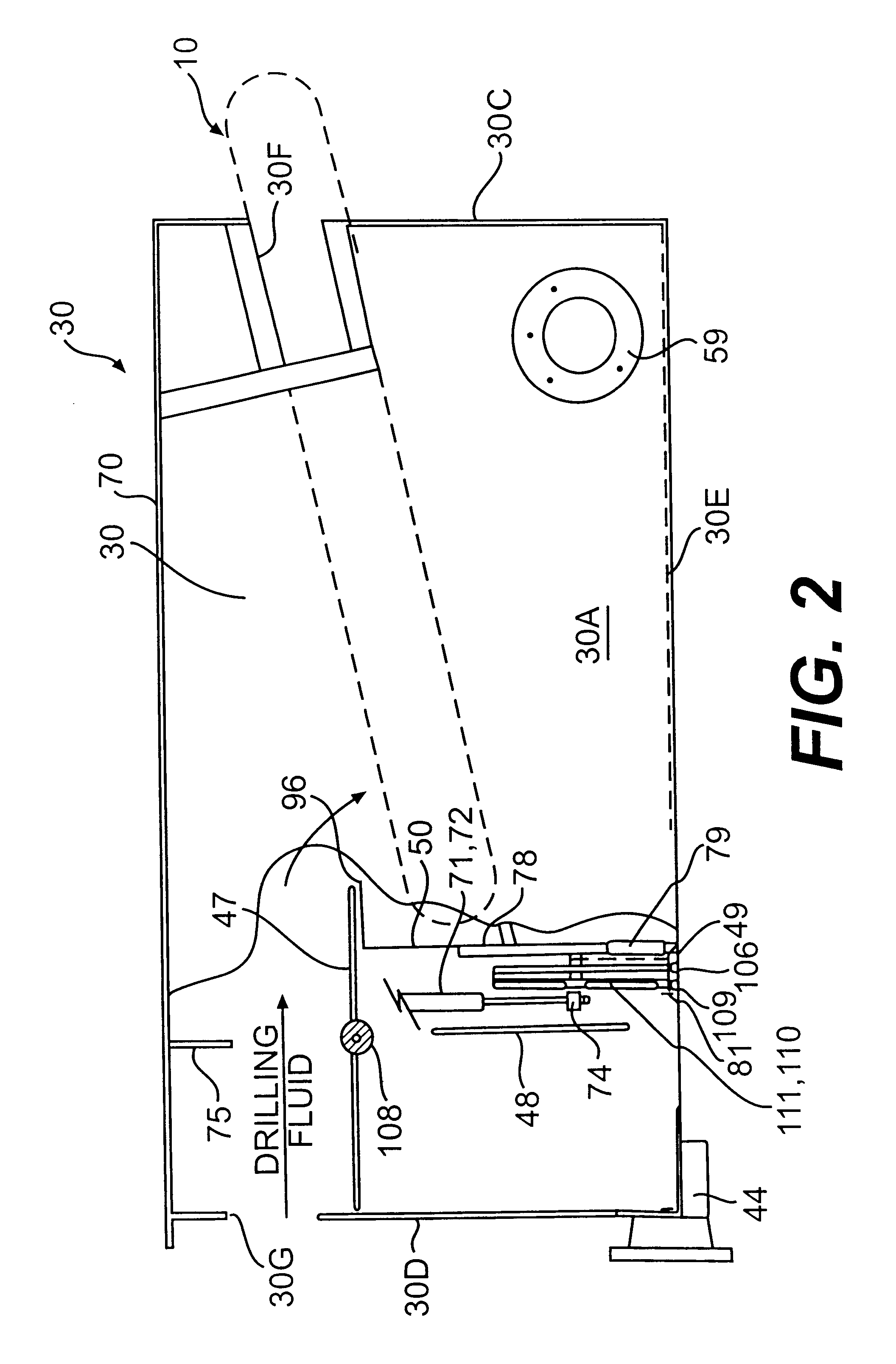
Referring now to FIGS. 1-4, the weir box 30 is a box-like housing having opposed side walls 30A and 30B, front end wall 30C (discharge end), back end wall 30D (inlet end), and a bottom wall 30E. The box 30 has a horizontal motor support plate 108 on one or both side walls on which a variable or fixed-speed drive motor with gearbox 63 is mounted to drive a drilling mud separation unit 10 (described hereinafter). A pair of elongate laterally opposed rails 52 are mounted on the inside of the opposed side walls and slidably receive and support the drilling mud separation unit 10 (shown in dashed line). The rails 52 are fixed in the weir box at an angle that is preferably from about 70.degree. to about 80.degree. from vertical, measuring from the back wall 30D, or any other suitable angle. The side walls also have cutouts 30F at their front ends to allow the front axle and drive sheave of the drilling mud separation unit to extend through either side of the weir box.

The box 30 has an ope...


PUM

PropertyMeasurementUnit
Flow rateaaaaaaaaaa
Volumeaaaaaaaaaa

Abstract

A weir box disposed upstream from conventional solids control equipment of a mud system of a drilling rig contains a drilling mud separation unit having a continuous-loop scalper screen that is driven in a continuous loop to separate, convey and discharge large amounts of gumbo, heavy clays and drill solids at the end of the separation unit. The flow divider box is a box-like housing with a diverter plate, weir baffle plates and a sliding gate that allows drilling fluid or drilling mud to be selectively directed to the mud separation unit to be separated prior to passing to the conventional downstream solids control equipment or allows the fluid to bypass the separation unit and flow directly to the conventional solids control equipment. The sliding gate is adjustable to selectively control or meter the flow rate and to create a hydrostatic head upstream from the conventional solids control equipment. The weir box baffle plates, sliding gate, and selective utilization of the mud separation unit allows the operator to produce an increased hydrostatic head, which enables high flow rates to be easily processed by shale shakers and other conventional downstream solids control equipment of the mud system and to compliment the drilling operation with respect to changes in the lithology, geological formations, or loss of returns in relation to the gallons pumped or volume of drilling fluid or drilling mud entering the weir box.

Description

1 . Field of the InventionThe invention relates to drilling mud control equipment, and more particularly to a weir box with a diverter plate, weir baffle plates and a sliding gate that allows drilling fluid or drilling mud to be selectively directed to a drilling mud separation unit contained therein or to bypass the separation unit prior to passing to conventional downstream solids control equipment and to selectively control and meter the flow rate and create a hydrostatic head upstream from the conventional solids control equipment.2. Brief Description of the Prior ArtThe mud system is an integral part of an oil and gas drilling rig, land or marine. Drilling mud or drilling fluid is continually recycled because of the huge cost factor and for environmental reasons. The drilling mud or drilling fluid is used to hold formation pressures in balance, to create and maintain well bore filter cake, create hydraulic horsepower at the bit, hydrostatic testing, shifting of spherical valve ...

Claims


Application Information

Patent Timeline
IPC IPC(8): B01D33/04E21B21/06E21B21/00
CPCB01D33/04E21B21/065B01D33/0565B01D33/722B01D33/801
Inventor WILLIAMS, J. TERRELL
Owner WILLIAMS J TERRELL
Why Eureka
Try Eureka