Eureka AIR delivers breakthrough ideas for toughest innovation challenges, trusted by R&D personnel around the world.

Internal gear pump

a gear pump and gear shaft technology, applied in the field of rotating pumps, can solve the problems of unsatisfactory noise suppression, uneven gap, and unsatisfactory noise suppression

Inactive Publication Date: 2001-06-12
SUMITOMO ELECTRIC SINTERED ALLOY LTD
View PDF5 Cites 39 Cited by
  • Summary
  • Abstract
  • Description
  • Claims
  • Application Information

AI Technical Summary

Problems solved by technology

Pressure pulsation of a hydraulic fluid, i.e. pulsation of discharge flow applies a vibrating force to the inner and outer gears, thus causing the teeth of these gears to collide against each other in radial and tangential directions, thus producing undesirable noises.
Thus, the gap is not uniform.
Noise suppression is thus not satisfactory.
Such pointed tips tend to be chipped, increase the surface pressure represented by Hertzian stress, and promote wear of the tooth surface.
In an ordinary internal gear pump, runout of the drive shaft coupled with the inner gear also causes noises and wear.
Due to non-uniformity of the gaps between teeth, the teeth of the inner and outer gears tend to collide against each other.
Further, in the structure in which the gear teeth tend to collide against each other, a marked increase in the pulsation of discharge flow due to cavitation resulting from collapse of liquid or gas bubbles in the pumping chamber tends to promote such collision between gear teeth and thus increase noise and wear of tooth surface.

Method used


Image

  • Internal gear pump
  • Internal gear pump
  • Internal gear pump

Examples


Embodiment Construction

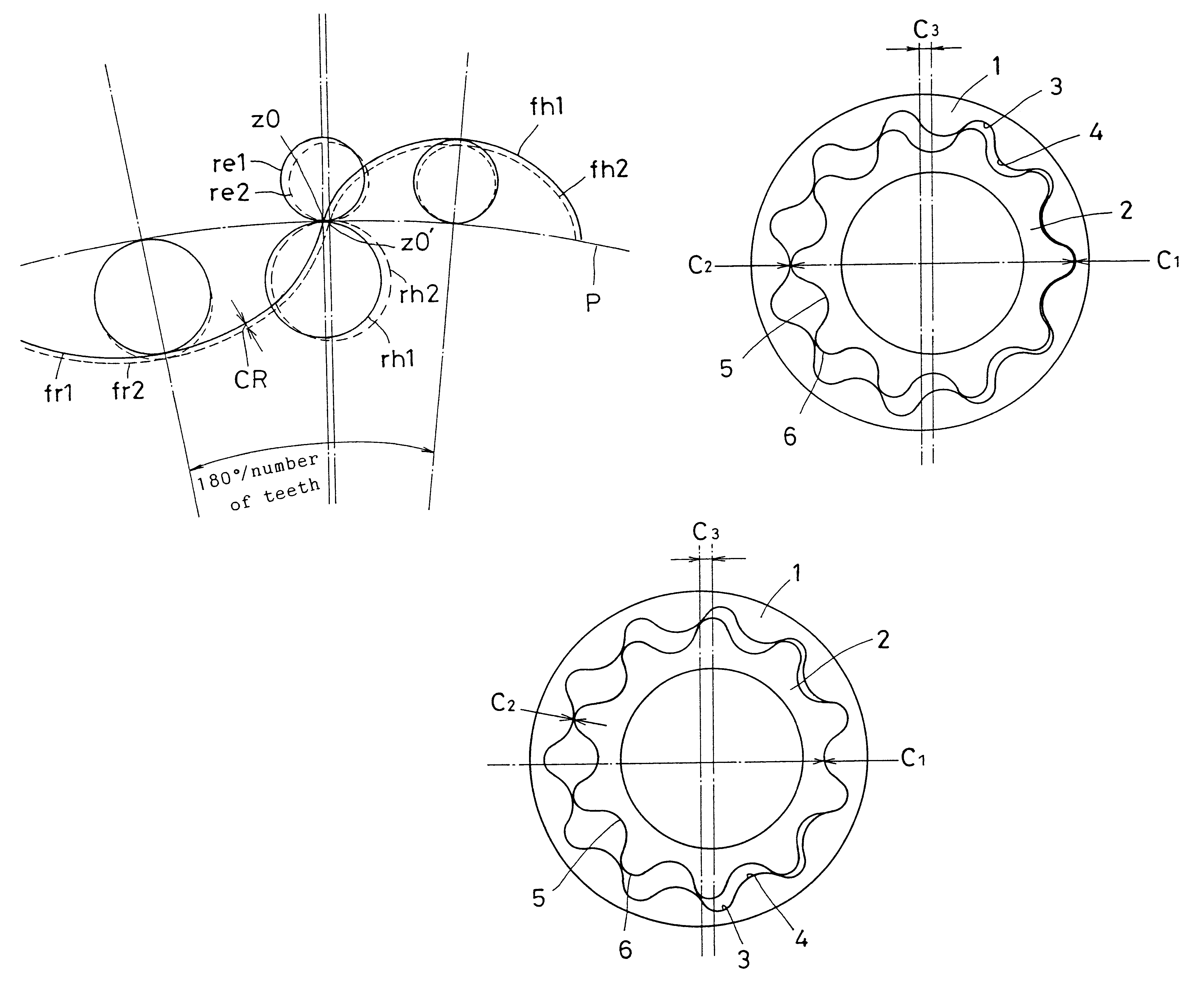
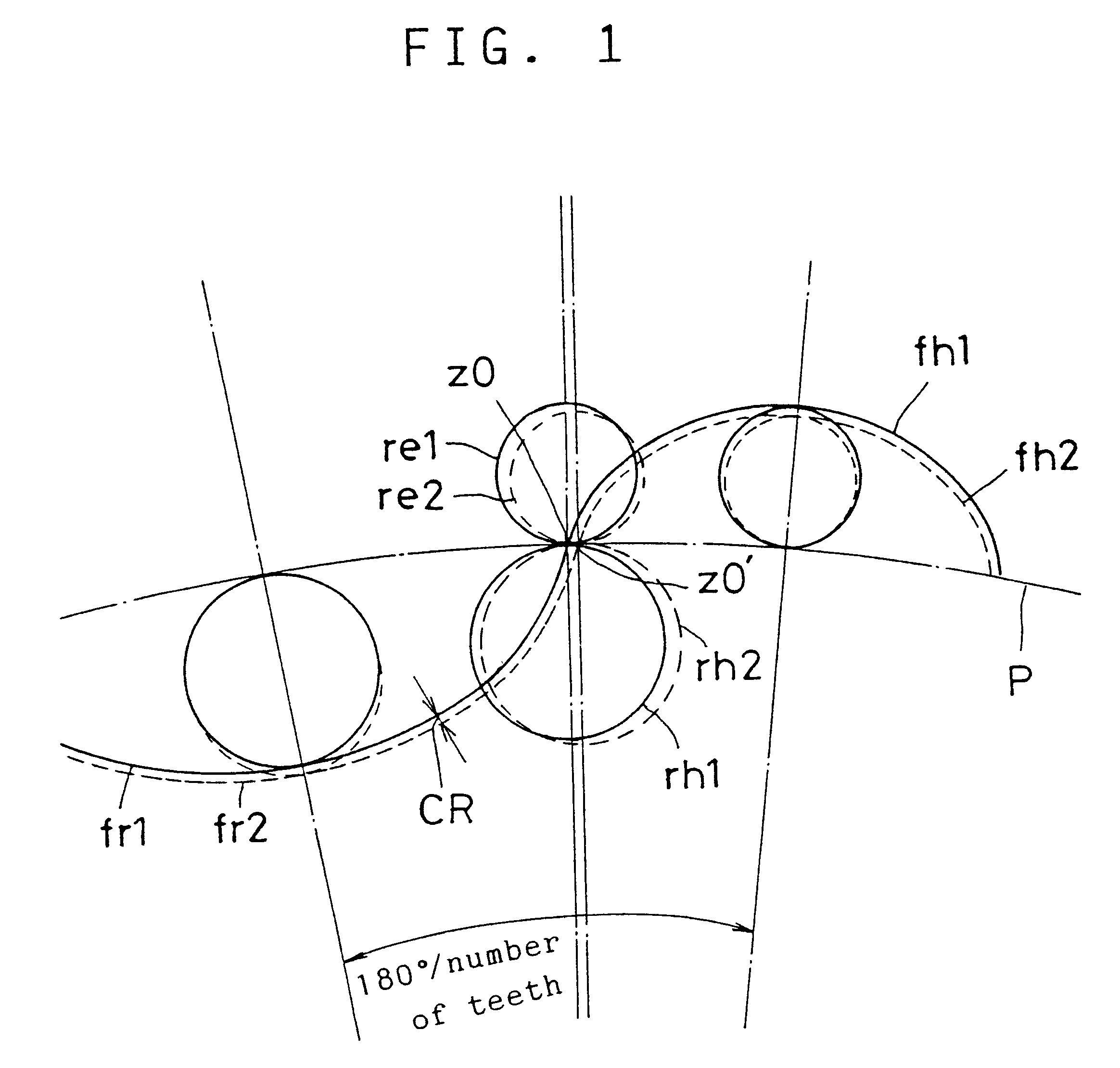
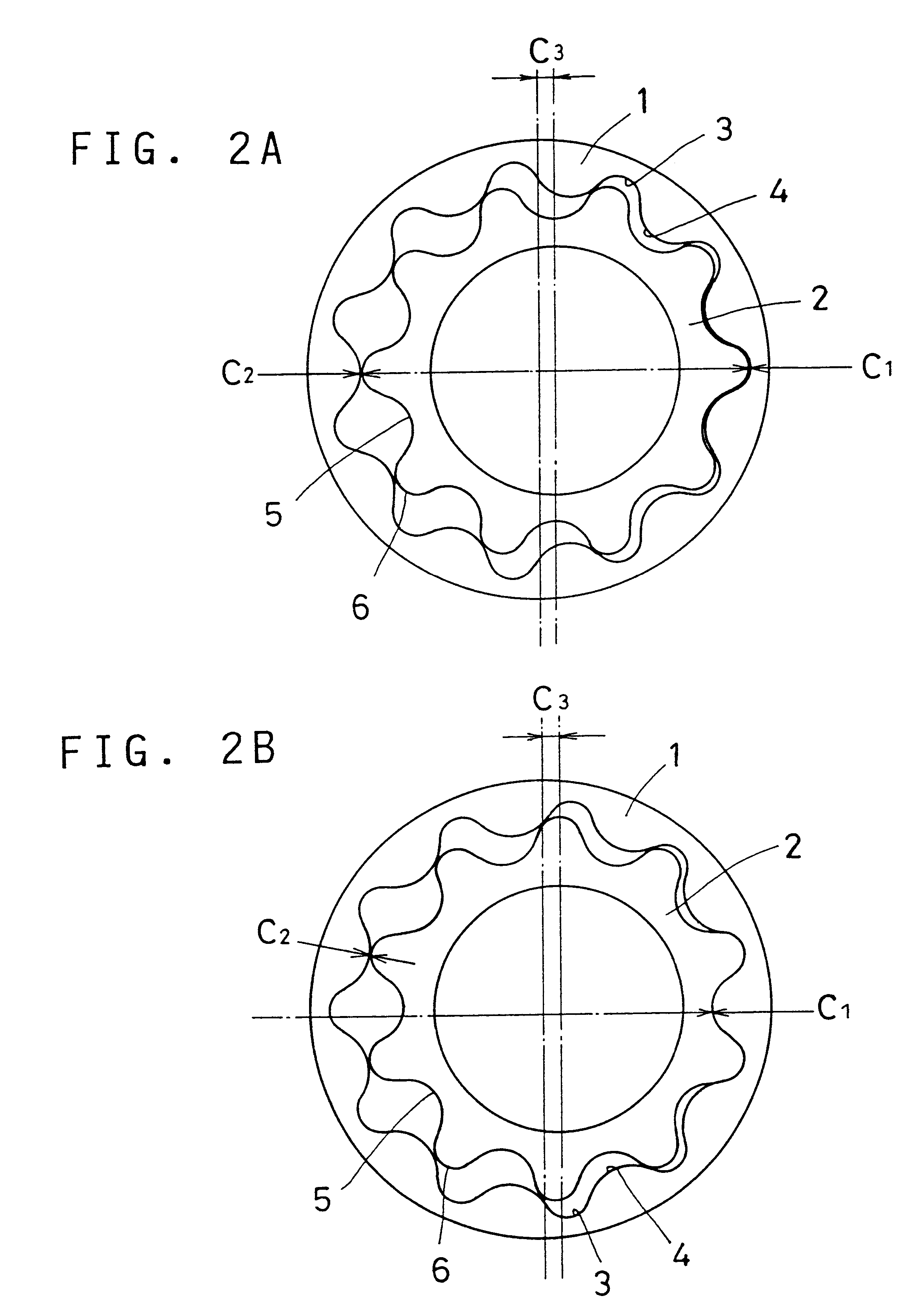
FIG. 1 shows a preferred embodiment of the present invention. fh1 and fr1 show an epicycloid and a hypocycloid, respectively, defining the shapes of tooth spaces 3 and tooth tips 4 of an outer gear 1 shown in FIG. 2. fh1 is formed as the locus of a point on the circumference of a generated circle re1 when the circle re1 rolls on a pitch circle P from a point z0 on the pitch circle. Similarly, fr1 is formed as the locus of a point on the circumference of a generated circle rh1 when the circle rh1 rolls on the pitch circle P from the point z0 on the pitch circle.

fh2 and fr2 represent an epicycloid and a hypocycloid, respectively, defining the shapes of the tooth tips 6 and tooth spaces 5 of the inner gear 2 shown in FIG. 2. fh2 is formed as the locus of a point on the circumference of a circle re2 when the circle re2 rolls on the pitch circle P from a point z0' on the pitch circle. Similarly, fr2 is formed as the locus of a point on the circumference of a circle rh2 when the circle rh...


PUM


Abstract

An internal gear pump which improves the mechanical efficiency and the life and reduces noises by eliminating non-uniformity of the gaps between teeth. In the internal gear pump wherein the tooth spaces of the outer gear and the tooth tips of the inner gear form an epicycloid and the tooth tips of the outer gear and the tooth spaces of the inner gear form a hypocycloid, these cycloids are formed by four circles that roll on the pitch circle of each gear such that the gap between teeth in a region where the outer and inner gears mesh most deeply with each other is substantially equal to the gap between teeth in a region where the depth of mesh between the outer and inner gears are the shallowest.

Description

TECHNOLOGICAL FIELDThe present invention relates to a rotary pump driven by a driving source such as a motor for compressing and discharging liquid or gas, and particularly an internal gear pump suitable for use as a liquid pump.BACKGROUND TECHNOLOGYMost internal gear pumps used in vehicle transmissions by internal combustion engines and automatic motors use trochoidal teeth. With trochoidal teeth, the tooth surface of one of the outer and inner gears is arcuately defined while the tooth surface of the other gear is defined by non-slip rotation of the arcuately defined teeth of the one gear.The internal gear pump according to the present invention uses a cycloidal tooth profile to discharge liquid or gas in an internal combustion engine or an automatic transmission. Such a pump is described in e.g. U.K. patent 233423 and German patent 3938346. The pump of the German patent is an internal gear pump having an outer gear (outer rotor) and an inner gear (inner rotor) having different nu...

Claims


Application Information

Patent Timeline
Patent Type & Authority Patents(United States)
IPC IPC(8): F04C2/00F04C2/10F04C2/08
CPCF04C2/084F04C2/102F04C2/10
Inventor KOSUGE, TOSHIYUKI
Owner SUMITOMO ELECTRIC SINTERED ALLOY LTD
Why Eureka
Eureka Blog
Learn More