
Tire retreading machine

a tire retreading machine and tire technology, applied in the direction of tyre parts, transportation and packaging, other domestic articles, etc., can solve the problems of redundancy of drive units, irregular wear of buffer blades on operation, and often complex adjustments of machines

Inactive Publication Date: 2001-06-26
RECAMIC SA
View PDF21 Cites 50 Cited by
  • Summary
  • Abstract
  • Description
  • Claims
  • Application Information

AI Technical Summary

Benefits of technology

Such a machine makes it possible, by the combination of two simple translational movements, to obtain buffing profiles of the surface of the crown of a tire. The fact that any relative displacement between the axis of rotation of the chuck and the center of the buffing tools is contained in a single plane passing through the axis of rotation of the chuck has the advantage of remarkably simplifying the interpretation of each displacement, since any moving closer, by five millimeters, for example, will correspond to a reduction of radius of the tire precisely equal to five millimeters. Any relative displacement can thus be directly linked to a thickness of rubber to be removed.
The invention further concerns a machine for retreading tires comprising a rotary chuck on which the tire to be treated is mounted, means of application of a tread and means of rolling down said tread after its application, characterized in that the chuck is mounted on a first carriage guided in vertical rails and moved by a first motor, in that the means of application of a tread and the means of rolling down said tread after its applications are borne by a second carriage guided in horizontal rails oriented parallel to the axis of rotation of said chuck and moved by a second motor, and in that means are provided for precisely positioning the first carriage relative to the second carriage.

Problems solved by technology

Those machines often contain complex adjustments for enabling the whole variety of necessary buffing profiles to be obtained.
The tire treated remains on the same chuck during buffing and molding, that is, application of the new tread, but without any interaction of the different parts of the machine, which results in a redundancy of drive units, and the need to mark several times the respective positions of the carcass and of the tread of the tire in the course of the successive operations.
In fact, it is well known that the blades of a buffer wear irregularly on operation.
This operation is particularly tedious.
Such contamination by particles coming off the blades of the buffer would be unacceptable.

Method used


Image

  • Tire retreading machine
  • Tire retreading machine
  • Tire retreading machine

Examples


Embodiment Construction

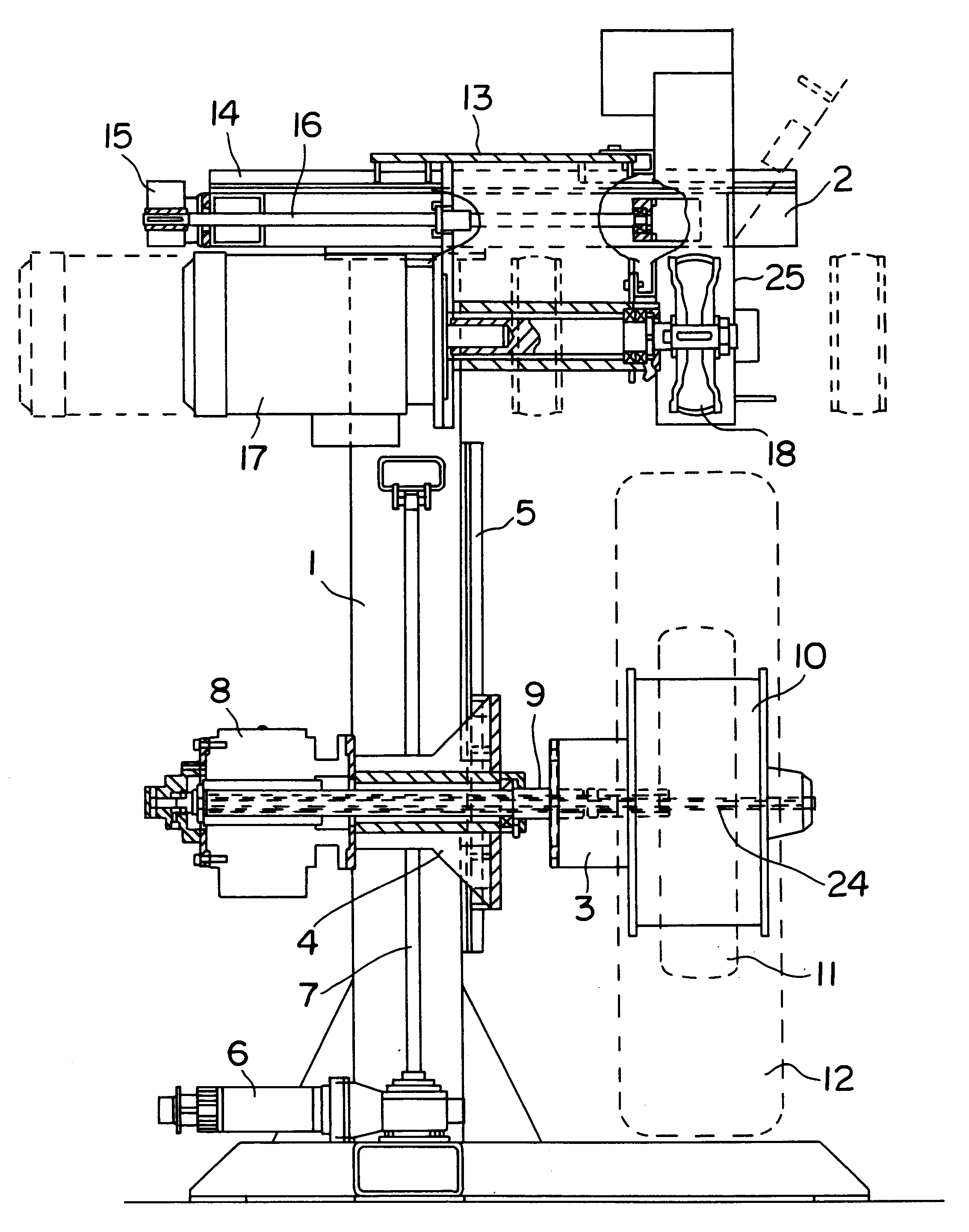
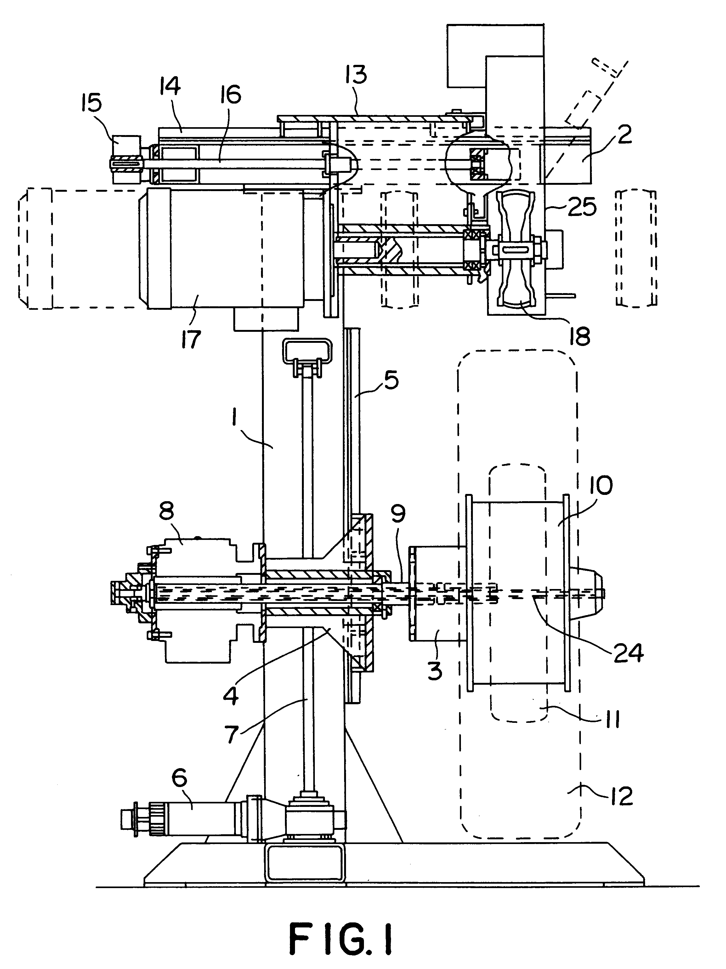
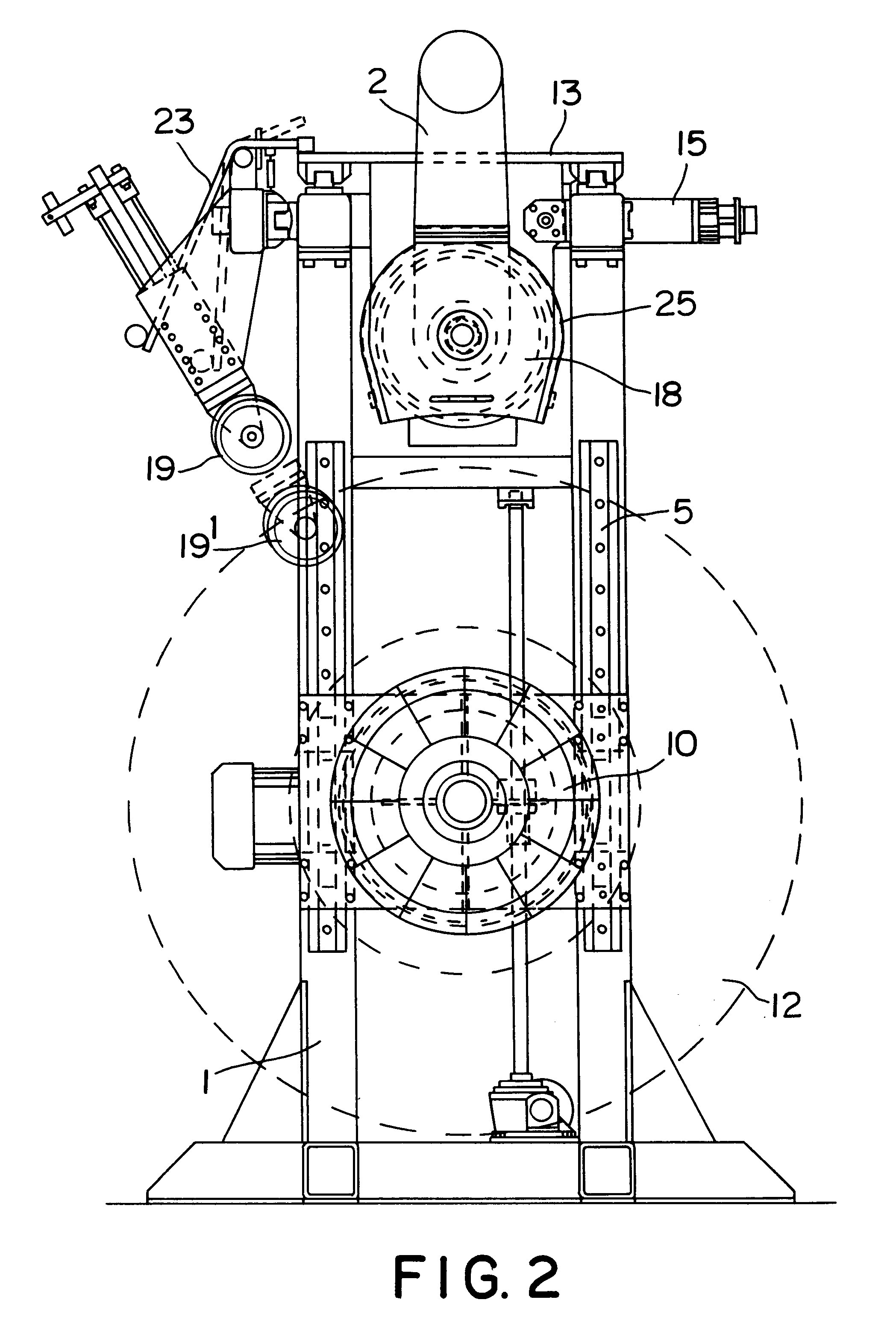
FIGS. 1 to 3 show a detreading-retreading machine according to the invention. The machine includes buffing tools as well as means of application and rolling down of a new tread. Such a machine is intended for small shops for which the combination of buffing and molding operations on the same work station entails a saving of space and time. On the other hand, for larger shops, it is advantageous to have two machines, a first one with buffing tools and a second with means for application and rolling down of a new tread. In the latter case, these two machines can have identical frames and control means, as described below

As can be seen in FIG. 1, the detreading-retreading machine comprises a vertical rigid frame 1 and a horizontal bracket 2. According to the invention, a chuck 3 is mounted on a carriage 4 guided in vertical rails 5 and moved by a step motor 6 and an endless screw 7. The carriage 4 carries a motor 8 mounted on the same shaft 9 as the chuck 3 in order to be able to drive...


PUM


Abstract

A machine for retreading tires, including a rotary chuck on which the tire to be treated is mounted and buffing tools, in which the chuck is mounted on a first carriage guided in rails and moved by a first motor, the buffing tools are carried by a second carriage guided in rails oriented parallel to the axis of rotation of the chuck and moved by a second motor, and in which provision is made for precisely positioning the first carriage relative to the second carriage and any relative displacement between the axis of rotation of the chuck and the center of the buffing tools is contained in a single plane passing through the axis of rotation of said chuck.

Description

BACKGROUND OF INVENTIONThe present invention relates to a machine for retreading tires; the invention concerns, in particular, a buffer as well as a combined machine further containing means for application and rolling down of the treads.It is known that most tires can be retreaded, that is, it is possible--after normal wear of the tread --to replace that tread and even some of the plies reinforcing the belt of the tire. Such operations are very common for truck tires; they can be carried out in factories or at relatively large shops.Numerous machines designed to remove remains of the tread from worn tires, a "detreading" operation, have been proposed. Among them, many use a buffer to carry out that detreading.Such a buffer consists of a series of blades containing cutting teeth on the outside and arranged side by side. Such a machine is disclosed in U.S. Pat. No. 4,116,256. Those machines often contain complex adjustments for enabling the whole variety of necessary buffing profiles...

Claims


Application Information

Patent Timeline
IPC IPC(8): B29D30/52B29D30/54
CPCB29D30/54B29C2793/0081B29D2030/541Y10S156/909
Inventor ANDERSSON, THOMASREPPEL, EMIL WILLI
Owner RECAMIC SA
Learn More