
Acoustic Testing Apparatus For Testing A Laminate Material And An Acoustic Testing Method For Testing A Laminate Material

a technology of acoustic testing and laminate materials, which is applied in the direction of reradiation, solid and fluid analysis using sonic/ultrasonic/infrasonic waves. it can solve the problems of inability to provide information about the depth of defects in the material, the inability of reflection testing techniques to be considered as viable options for testing laminate materials, and the complexity of detected reflection images. it can achiev

Inactive Publication Date: 2007-08-30
NEDERLANDSE ORG VOOR TOEGEPAST-NATUURWETENSCHAPPELIJK ONDERZOEK (TNO)
View PDF6 Cites 7 Cited by
  • Summary
  • Abstract
  • Description
  • Claims
  • Application Information

AI Technical Summary

Benefits of technology

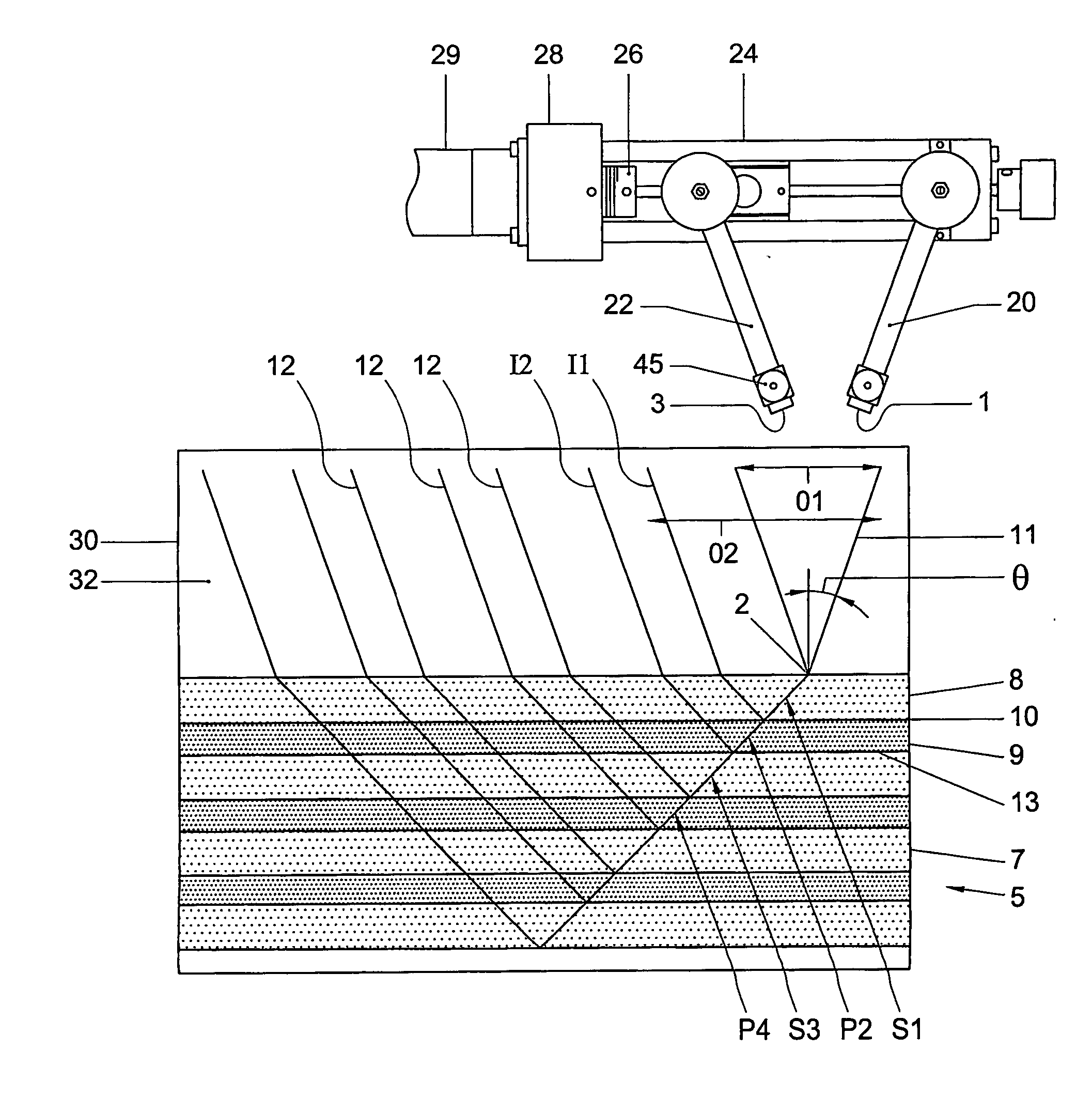
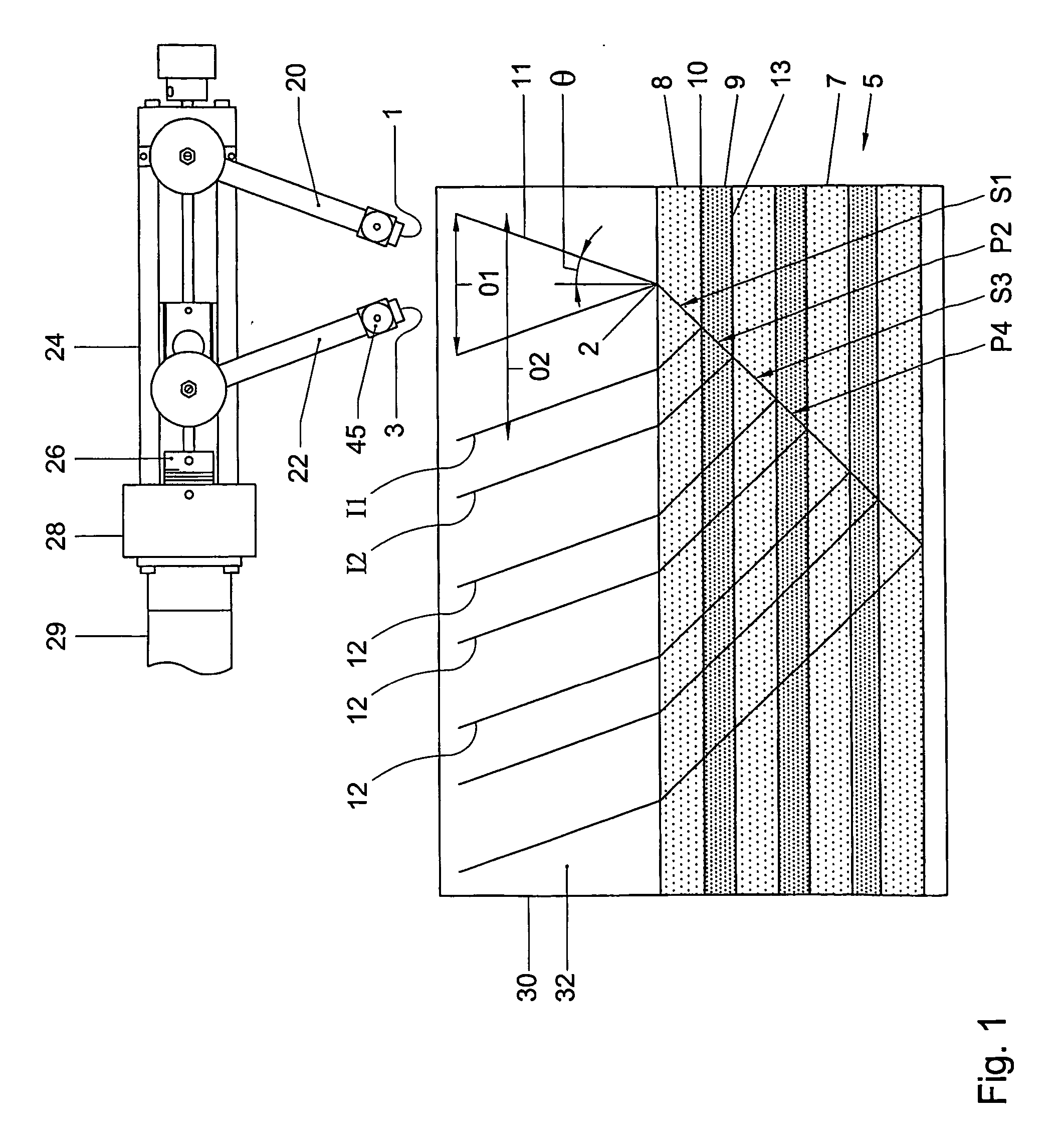
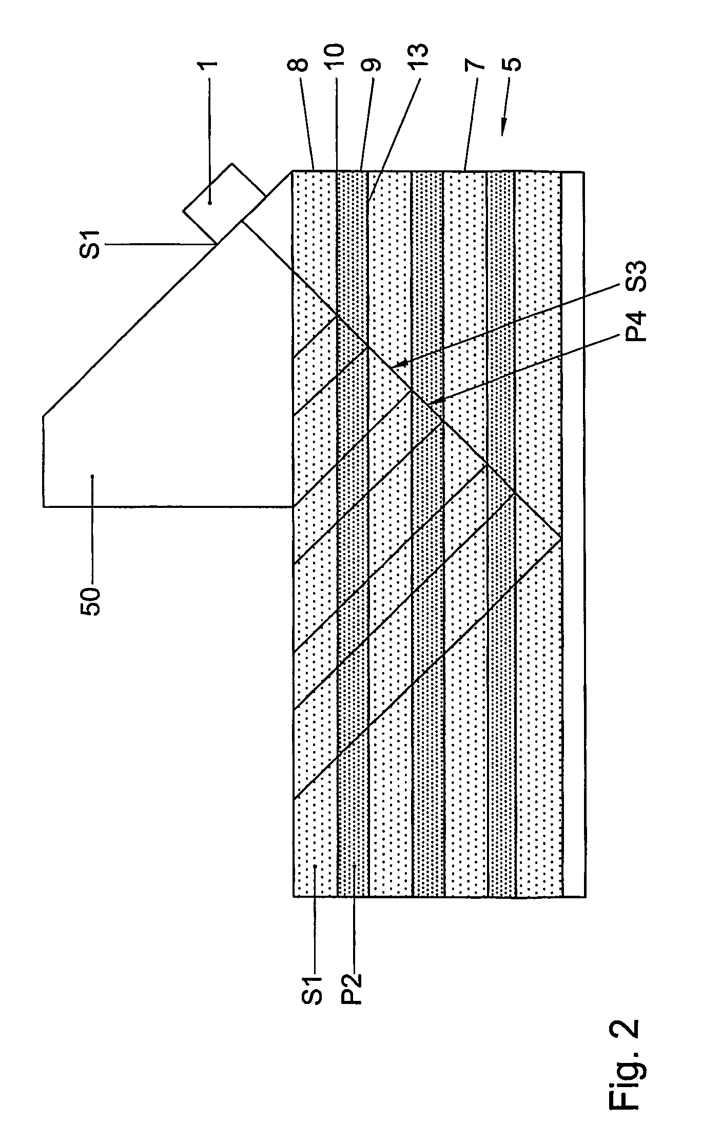
[0006] The inventors have found that for most laminate materials, the shear wave (S-wave) velocity in the material of one layer is approximately the same as the compression wave (P-wave) velocity in the material of its surrounding layers. Consequently, if an S-wave is projected under a given (non-0 degree) angle into a layer of the first material, the S-wave is converted into a P-wave travelling into the second layer at the interface with a layer of the second material from the interface, travelling at the same angle corresponding to the angle of incidence. Consequently, there is no refraction at the interface, but there are reflections at every boundary between adjacent layers. Because no refraction occurs at the boundary between adjacent layer, the laminate material appears homogenous to the receiver, thus interpretation of the reflected test signal is greatly simplified. The present invention is based on the insight that the material properties, in particular, the elastic properties, of the laminate material can be exploited to project a test signal which when reflected by the laminate material comprises data where the structural features are directly visible in the collected data.
[0015] In a preferred embodiment, a plurality of second transducers arranged in an array. By providing an array of second transducers reflection data may be received from a plurality of locations simultaneously. Thus, increasing the speed and accuracy of data acquisition.

Problems solved by technology

These techniques lack the capability of providing information about the depth of defects in the material.
Although some reflection techniques provide some information about the depth of defects, it has been found that, due to the fine layering of laminate materials, the detected reflection images are often very complicated and difficult to process due to the vast number of reflections.
Thus, reflection testing techniques have not been considered as a viable option for testing laminate materials.

Method used


Image

  • Acoustic Testing Apparatus For Testing A Laminate Material And An Acoustic Testing Method For Testing A Laminate Material
  • Acoustic Testing Apparatus For Testing A Laminate Material And An Acoustic Testing Method For Testing A Laminate Material
  • Acoustic Testing Apparatus For Testing A Laminate Material And An Acoustic Testing Method For Testing A Laminate Material

Examples


Embodiment Construction

[0024] The acoustic testing apparatus shown in FIG. 1 comprises a source 1, typically including a first transducer, for projecting a test signal 11 onto a laminate material 7 in a test zone 5. Also provided is a receiver 3, typically including a second transducer, for receiving a test signal 12 having passed through the test zone 5. The receiver 3 is arranged to be disposed at least one location O1, O2, etc. Alternatively, a plurality of receivers may be disposed in an array in an acquisition plane. The test signal is incident on a surface of the laminate material 7 at least one location 2. For each location 2 several measurements are taken with varying distance O1, O2, etc, also referred to as offset, between the source 1 and the receiver 3. This provides an optimum depth resolution of the image. The laminate material 7 comprises a plurality of layers 8, 9. At the interface 10 between adjacent layers 8, 9 reflections of the test signal occur. Reflections from deeper layers occur at...


PUM

PropertyMeasurementUnit
angleaaaaaaaaaa
angleaaaaaaaaaa
frequencyaaaaaaaaaa

Abstract

An acoustic testing apparatus for testing a laminate material comprising at least one layer of a first material having a first velocity for a first vibration mode and at least one layer, adjacent to said first layer, of a second material having a velocity for a second vibration mode, approximately equal to said first velocity, said acoustic testing apparatus comprising: a first transducer for projecting an acoustic test signal onto a first layer of said at least one layer of a first material disposed in a testing zone, wherein a second transducer for receiving said test signal from said testing zone, and in that said first transducer is adapted to project said test signal at an angle so as to generate in said first layer vibrations of at least said first vibration mode, wherein said vibrations of said first vibration mode are incident on an interface with said layer of said second material under an incidence angle so as to produce in said second layer vibrations of at least said second vibration mode, so that refraction of said test signal at said interface is suppressed.

Description

TECHNICAL FIELD [0001] The invention relates to an acoustic testing apparatus for testing a laminate material and an acoustic testing method for testing a laminate material. BACKGROUND TO THE INVENTION AND PRIOR ART [0002] Acoustic testing is a technique which uses sound waves to test an object. Ultrasonic non-destructive testing is one such technique, which has found application in the testing of laminate materials, such as metal laminate systems used in the aerospace industry. Conventional non-destructive testing methods for laminates are based on transmission measurements or very low frequency reflection measurements. These techniques lack the capability of providing information about the depth of defects in the material. In conventional reflection techniques a single transmitter / receiver transducer is arranged to project an acoustic test signal which is incident on the test material at approximately zero degrees (it should be noted that incidence angles are measured with respect...

Claims


Application Information

Patent Timeline
Patent Type & Authority Applications(United States)
IPC IPC(8): G01N29/32G01N29/265G01N29/04G01N29/06
CPCG01N29/0618G01N2291/011G01N2291/0231G01N2291/0422G01N2291/2694G01N2291/044G01N2291/102G01N2291/103G01N2291/0428
Inventor VOLKER, ARNO WILLEM F.
Owner NEDERLANDSE ORG VOOR TOEGEPAST-NATUURWETENSCHAPPELIJK ONDERZOEK (TNO)
Learn More