
Enhanced ultrasound imaging interpretation and navigation

a technology of ultrasound imaging and navigation, applied in the field of enhanced ultrasound imaging interpretation and navigation, can solve the problems of user disorientation, ultrasound image may be too small to contain anatomical landmarks, and the depth of the picture is also generally limited to about 5-12 cm, so as to reduce the risk of misinterpretation, simplify the interpretation, and increase productivity. efficiency and accuracy

Inactive Publication Date: 2014-11-20
UNIV OF FLORIDA RES FOUNDATION INC
View PDF6 Cites 7 Cited by
  • Summary
  • Abstract
  • Description
  • Claims
  • Application Information

AI Technical Summary

Benefits of technology

The patent text describes a new ultrasound imaging system that can help medical professionals more easily and accurately interpret images and minimize the risk of misinterpretation. The system displays the ultrasound image with certain features, like correlated orientation and background fill, which can make it easier for medical professionals to interpret the images and navigate through them. This can lead to increased productivity and efficiency, while also promoting patient safety.

Problems solved by technology

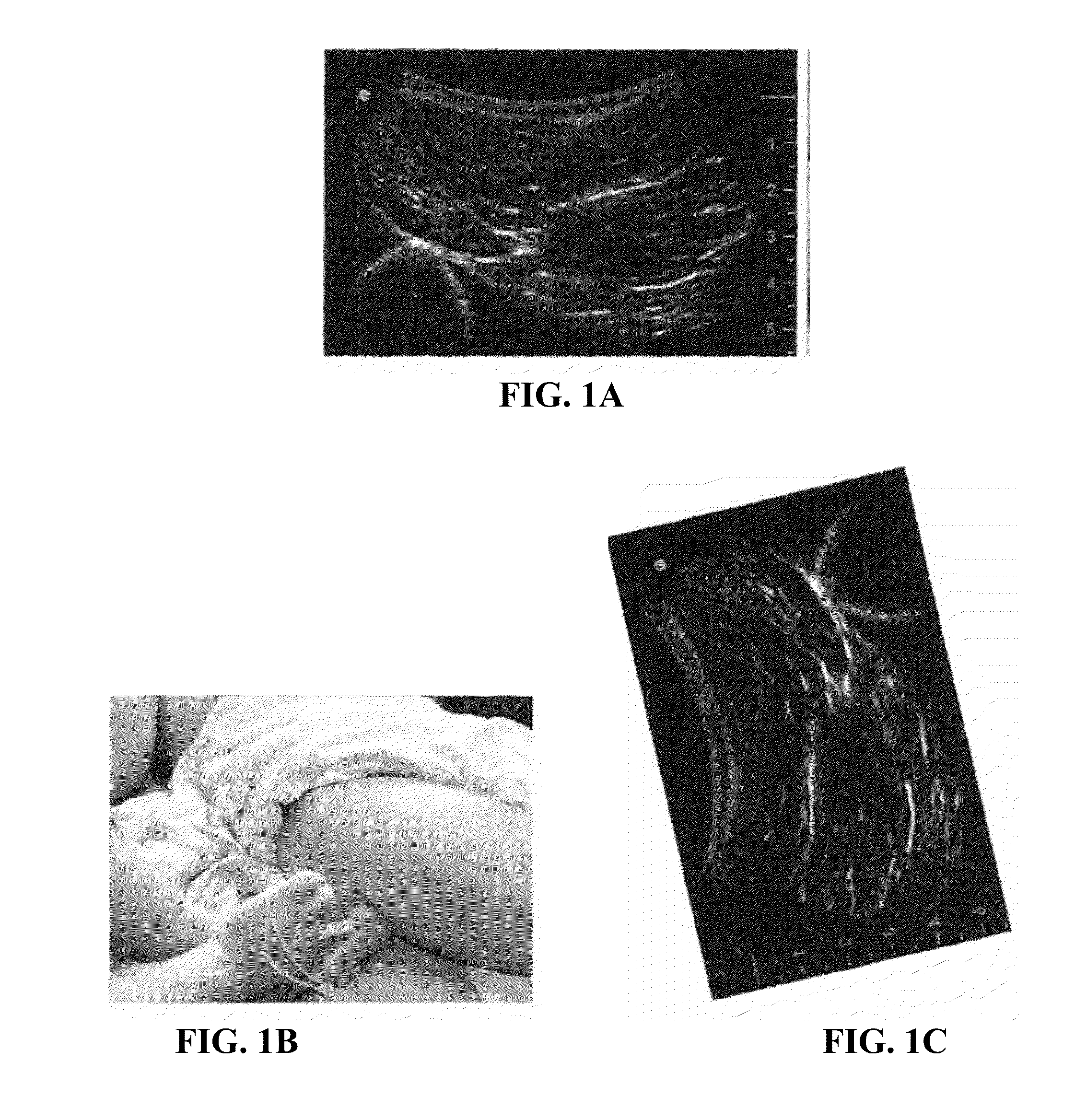
However, even if a clinician has a mental model of corresponding cross-sectional computed tomography (CT) or magnetic resonance imaging (MRI) image anatomy, it can sometimes be a challenge to match the structures on an ultrasound image with structures in the mental model.
Furthermore, the depth of the picture is also generally limited to about 5-12 cm.
Because the field of view from an ultrasound probe is limited, users may become disoriented, especially if they are used to larger images from CT and MRI.
In other words, the ultrasound image may be too small to contain anatomical landmarks that would help the user in obtaining his or her bearings and interpreting the ultrasound image.
Thus, if an anatomical structure is insonated from the side or from the bottom, a practitioner must do complex distracting; mental conversions / transformations / rotations of the image, and this is not easy and requires experience.
This also makes ultrasound-guided needle placement more difficult and unnatural.

Method used


Image

  • Enhanced ultrasound imaging interpretation and navigation
  • Enhanced ultrasound imaging interpretation and navigation
  • Enhanced ultrasound imaging interpretation and navigation

Examples


Embodiment Construction

[0018]Ultrasound imaging systems and techniques for facilitating interpretation of an ultrasound image are presented. In some embodiments, the orientation of an ultrasound image is automatically adjusted to correspond with a direction, orientation and / or position of insonation with respect to an anatomy. In some embodiments, background fill is provided based on the location and orientation of the ultrasound probe. In some further embodiments, the position of anatomical landmarks is recorded and displayed along with the ultrasound image.

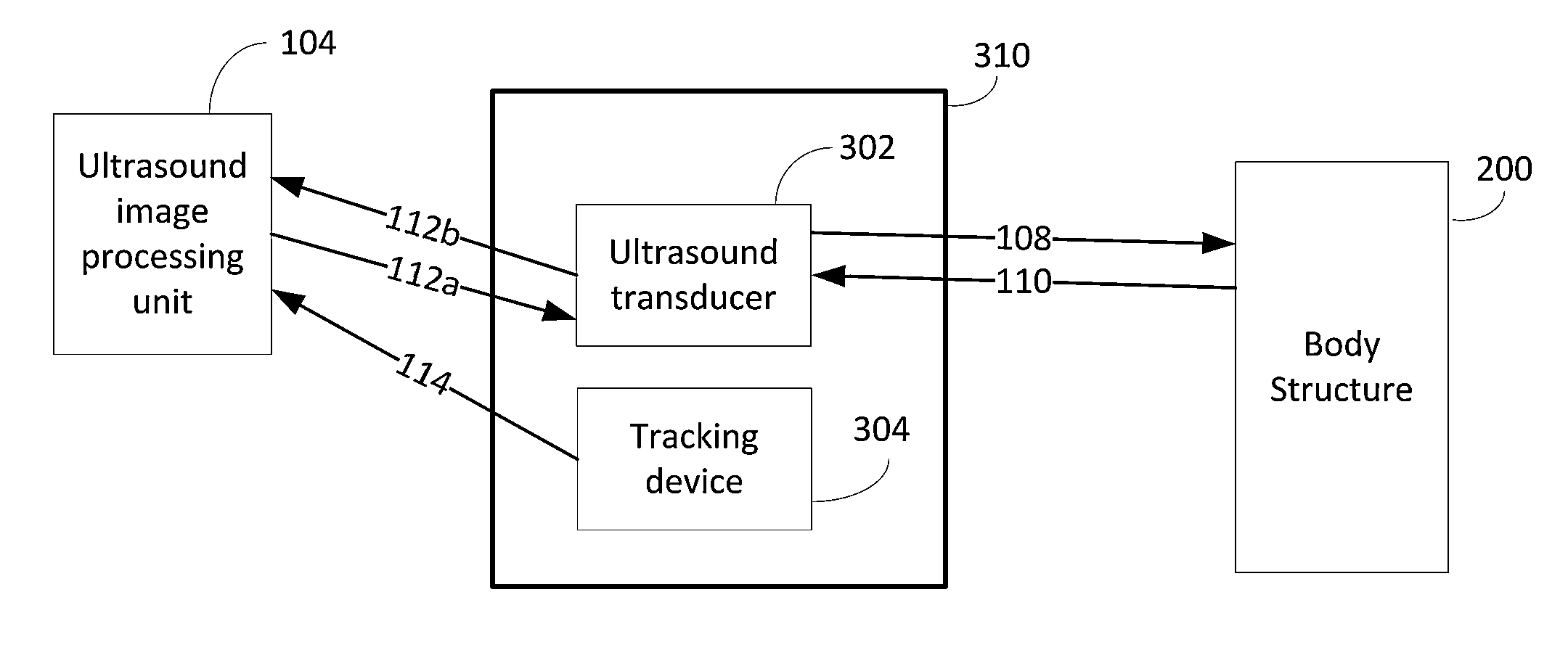
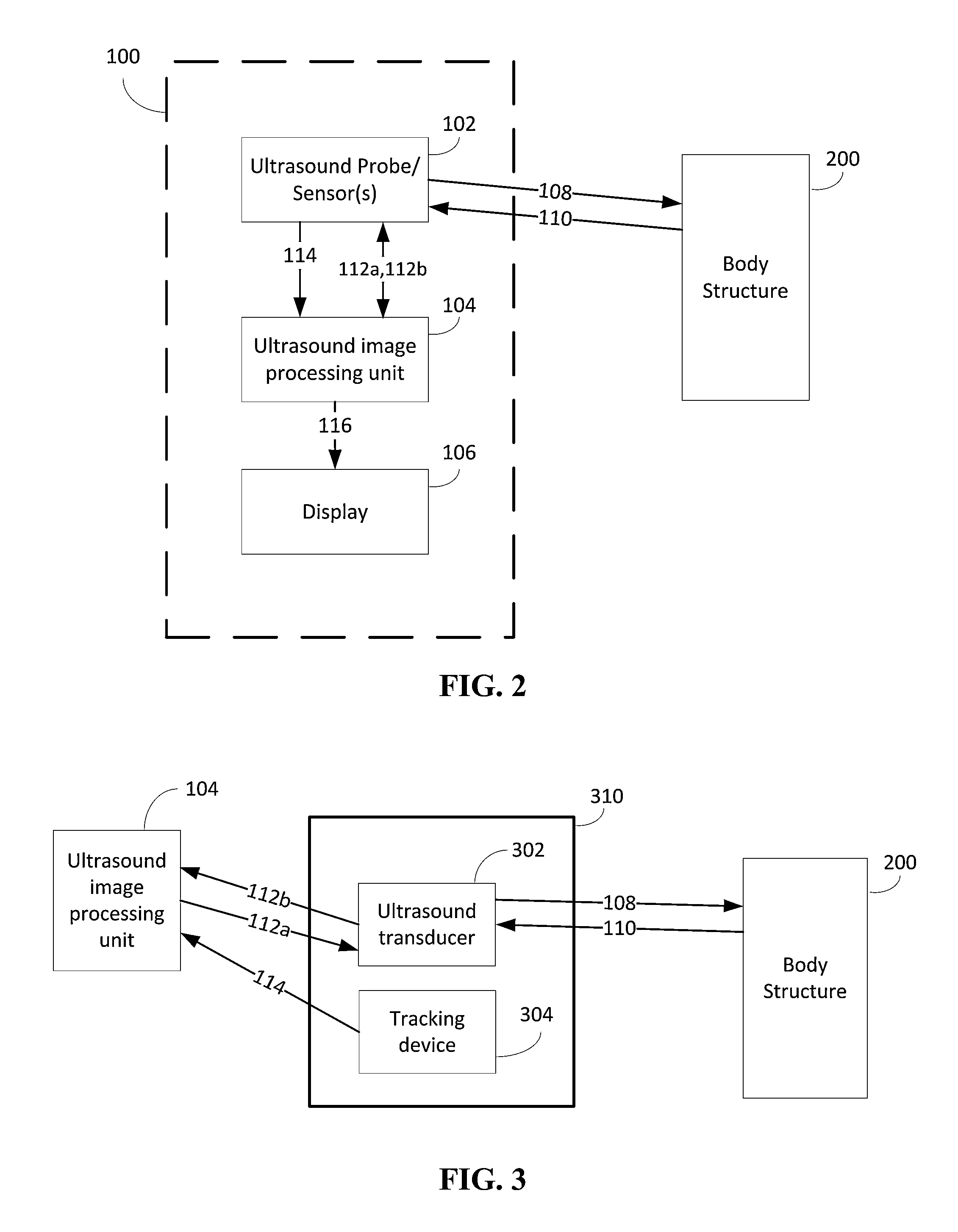
[0019]A system is provided in which the orientation of an ultrasonic image display is configured to match the ultrasound probe orientation for ease of interpretation. According to one embodiment, the position and the orientation in 3D space of a handheld ultrasound probe are tracked using one or more position and orientation sensors. The orientation of the ultrasound image displayed on a monitor (or display) is automatically adjusted to reflect the po...


PUM


Abstract

Systems and techniques are provided in which the orientation of an ultrasonic image display is configured to match the ultrasound probe orientation for ease of interpretation. The position and the orientation of an ultrasound probe are tracked using a tracking device having one or more position and orientation sensors. The orientation of a displayed ultrasound image is automatically adjusted to reflect the position and orientation of the ultrasound probe relative to the body structure being imaged. In some embodiments, a background image (with possible landmarks) is provided based on the location and orientation of the tracked ultrasound probe.

Description

CROSS-REFERENCE TO RELATED APPLICATION[0001]The present application claims the benefit of U.S. Provisional Application Ser. No. 61 / 824,559, filed May 17, 2013, which is hereby incorporated by reference herein in its entirety, including any figures, tables, or drawings.BACKGROUND[0002]Ultrasound imaging techniques that provide a real-time display of an imaged region are often used in operating room and diagnostic procedures. However, even if a clinician has a mental model of corresponding cross-sectional computed tomography (CT) or magnetic resonance imaging (MRI) image anatomy, it can sometimes be a challenge to match the structures on an ultrasound image with structures in the mental model. This occurs due to several reasons.[0003]One reason is that the ultrasound window (width of the image) is much smaller than the usual CT slice. For example, the typical ultrasound window is about 38-60 mm depending on the footprint size and type of the ultrasound probe (e.g., curved or linear). ...

Claims


Application Information

Patent Timeline
Patent Type & Authority Applications(United States)
IPC IPC(8): A61B8/08A61B8/00
CPCA61B8/4254A61B8/5292A61B8/0858A61B8/4245A61B8/461A61B8/523
Inventor IHNATSENKA, BARYS VALERIEVICHLAMPOTANG, SAMSUNLIZDAS, DAVID ERIKGRAVENSTEIN, DIETRICHBOEZAART, ANDRE
Owner UNIV OF FLORIDA RES FOUNDATION INC
Learn More