Polyhedral-shaped redundant coaxial switch

a coaxial switch, polyhedral technology, applied in the direction of dynamo-electric relays, electrical apparatus, contacts, etc., can solve the problems of inability to connect most or all of the redundant 1 to output 1, limited flexibility of the prior art switch assembly, etc., to reduce the number of switches required, reduce the number of intermediate paths, and reduce the weight

Inactive Publication Date: 2001-06-26
HUGHES ELECTRONICS
View PDF5 Cites 28 Cited by
  • Summary
  • Abstract
  • Description
  • Claims
  • Application Information

AI Technical Summary

Benefits of technology

The three-dimensional microwave switch of the present invention provides a significant weight reduction over the prior art by reducing the number of switches required in a switch assembly. The switch of the present invention reduces the number of intermediate paths a signal must travel over which ultimately provides improved RF performance. Independent actuation of the reeds in the switch of the present invention increases signal path flexibility.

Problems solved by technology

Also, it is only possible to connect Redundant 1 to Output 1.
This is one example of the limited flexibility of the prior art switch assembly.
Most or these connections are not possible in the prior art T-switch assembly.

Method used


Image

  • Polyhedral-shaped redundant coaxial switch
  • Polyhedral-shaped redundant coaxial switch
  • Polyhedral-shaped redundant coaxial switch

Examples


Embodiment Construction

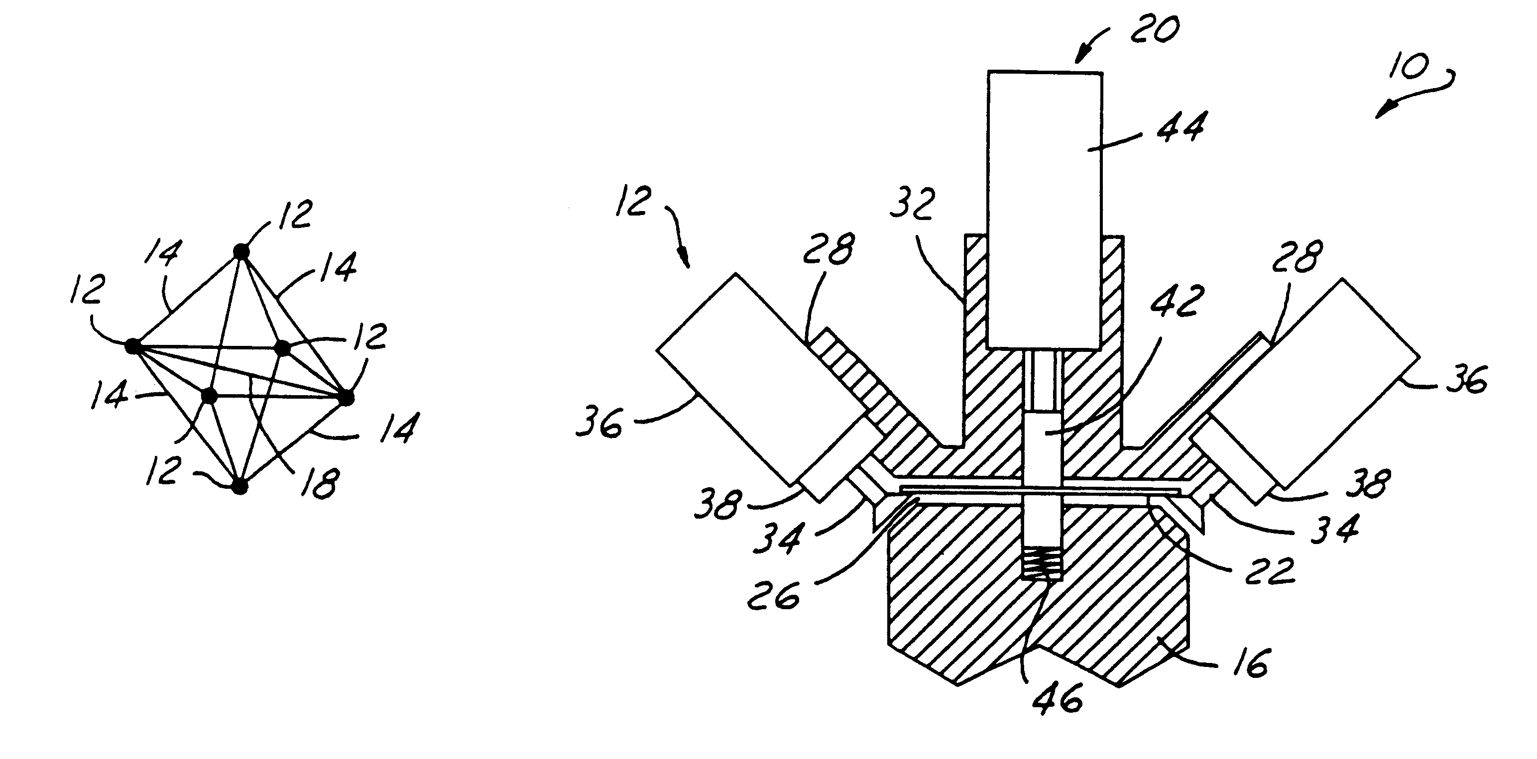
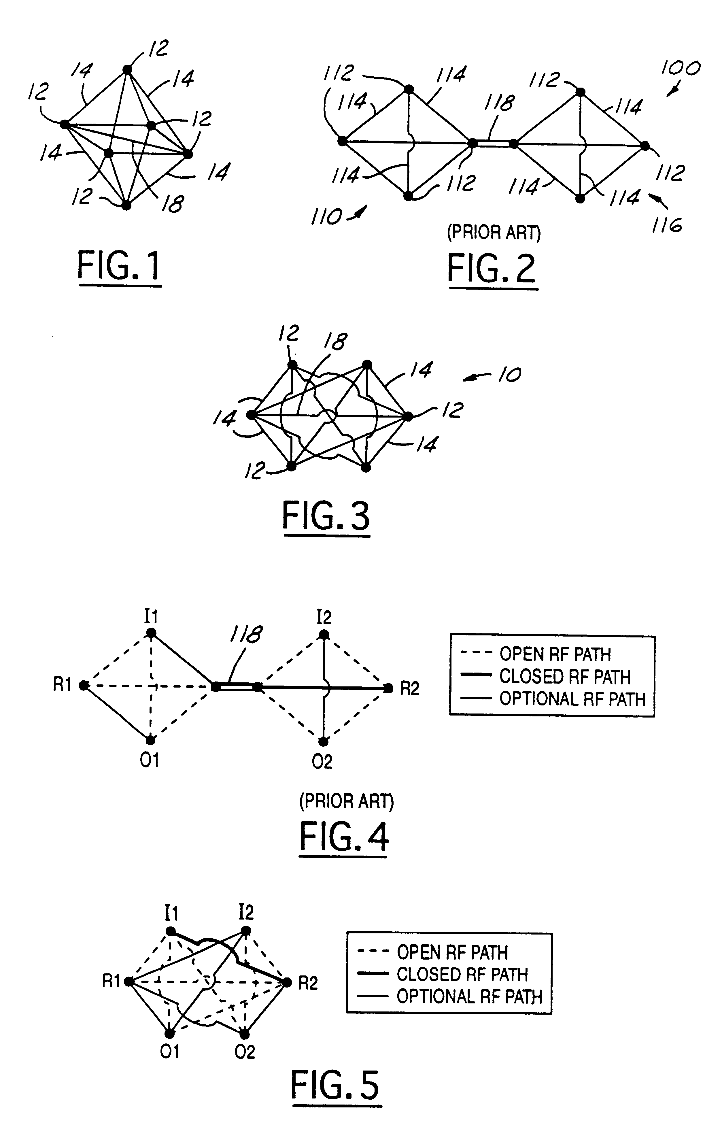
FIG. 1 is an isometric schematic of the microwave switch 10 of the present invention. The microwave switch has six ports 12 interconnected in an octahedral configuration by thirteen waveguide transmission lines 14. Twelve of the transmission lines 14 lie along the vertices of the octahedral shape. The thirteenth transmission line is a through path 18 passing through the interior of the octahedral shape and located between one pair of opposing ports 12. Each port 12 abuts up to four of the waveguide transmission lines 14, and two opposing ports may abut the through path transmission line 18.

The waveguide transmission lines 14 are interconnected in an octahedral configuration with the six ports 12 positioned at the corners of the octahedron. The waveguide transmission lines 14 are dimensioned to have a cutoff frequency, suitably 45 GHz, greater than the operating frequency band.

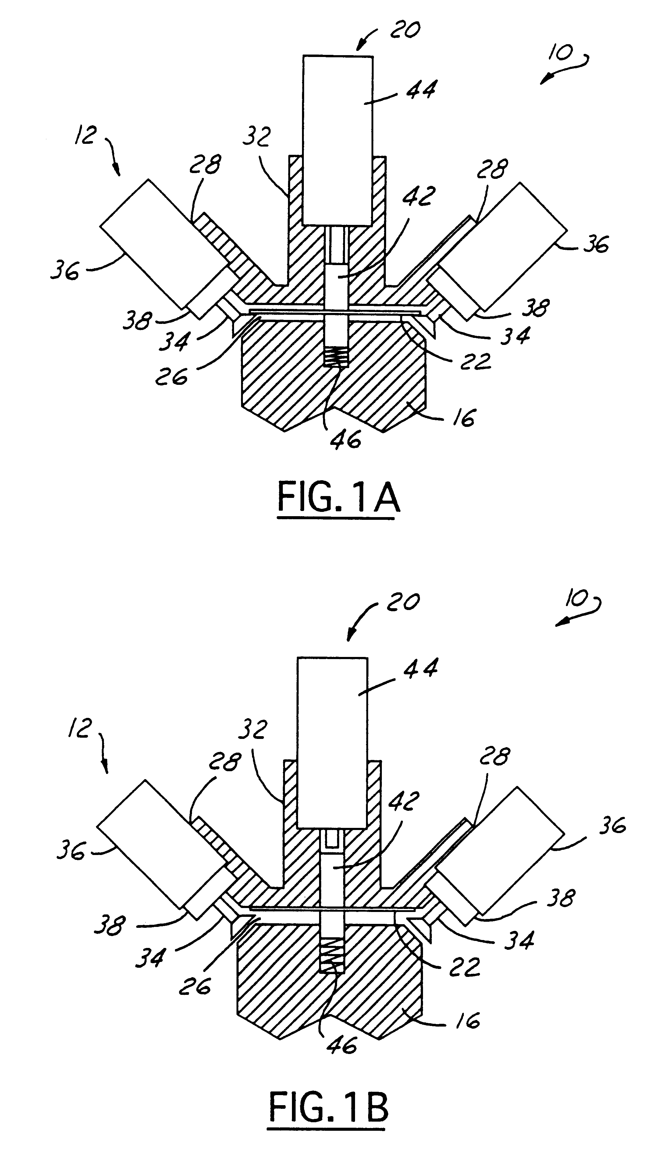
FIG. 1A is a partial view of the switch 10 of the present invention in the signal-conducting position. FIG. ...


PUM


Abstract

A three dimensional microwave switch having a plurality of waveguide transmission lines configured in an octahedral shape having microwave I/O ports at the corners. Individual actuators selectively move respective reeds within the waveguide transmission lines between a signal-attenuating position abutting the interior surface of the waveguide transmission line and a signal-conducting position substantially coaxial with the waveguide transmission line and abutting the signal lines of the I/O microwave ports couple to opposite ends of the waveguide transmission line.

Description

The present invention relates to microwave switches, and more particularly to three-dimensional (3D) microwave switches, specifically octahedral-shaped switches, for routing microwave signals along selectable signal paths among a plurality of switch ports.Microwave switches are used in redundant switching networks on spacecrafts to route M input signals to M outputs through N failure-prone devices, such as traveling wave tube amplifiers (TWTAS). This is accomplished using two layers of microwave switches, with each layer including M serial connected 4-port switches, for example, T-switches. The switches in the input layer are controlled to route the M input signals around the failed devices and through functioning devices. The switches in the output layer are controlled to route the signals produced by the M selected devices to the M outputs.Typically, planar T-switch configurations are used effectively in redundant switching networks on board spacecraft. However, there are a number...

Claims


Application Information

Patent Timeline
Patent Type & Authority Patents(United States)
IPC IPC(8): H01P1/12H01P1/10
CPCH01P1/122
Inventor ANDO, MICHAEL N.
Owner HUGHES ELECTRONICS
Why Eureka
Try Eureka