
Image detecting apparatus

a detection apparatus and image technology, applied in the field of image area extraction, can solve the problems of inaccurate extraction, poor accuracy, and inability to obtain correct results, and achieve the effect of accurately and efficiently extracting the desired area from the imag

Inactive Publication Date: 2001-06-26
SONY CORP
View PDF15 Cites 28 Cited by
  • Summary
  • Abstract
  • Description
  • Claims
  • Application Information

AI Technical Summary

Benefits of technology

In view of the foregoing, an object of this invention is to provide an image area extracting method capable of extracting the desired area from the image accurately and efficiently.
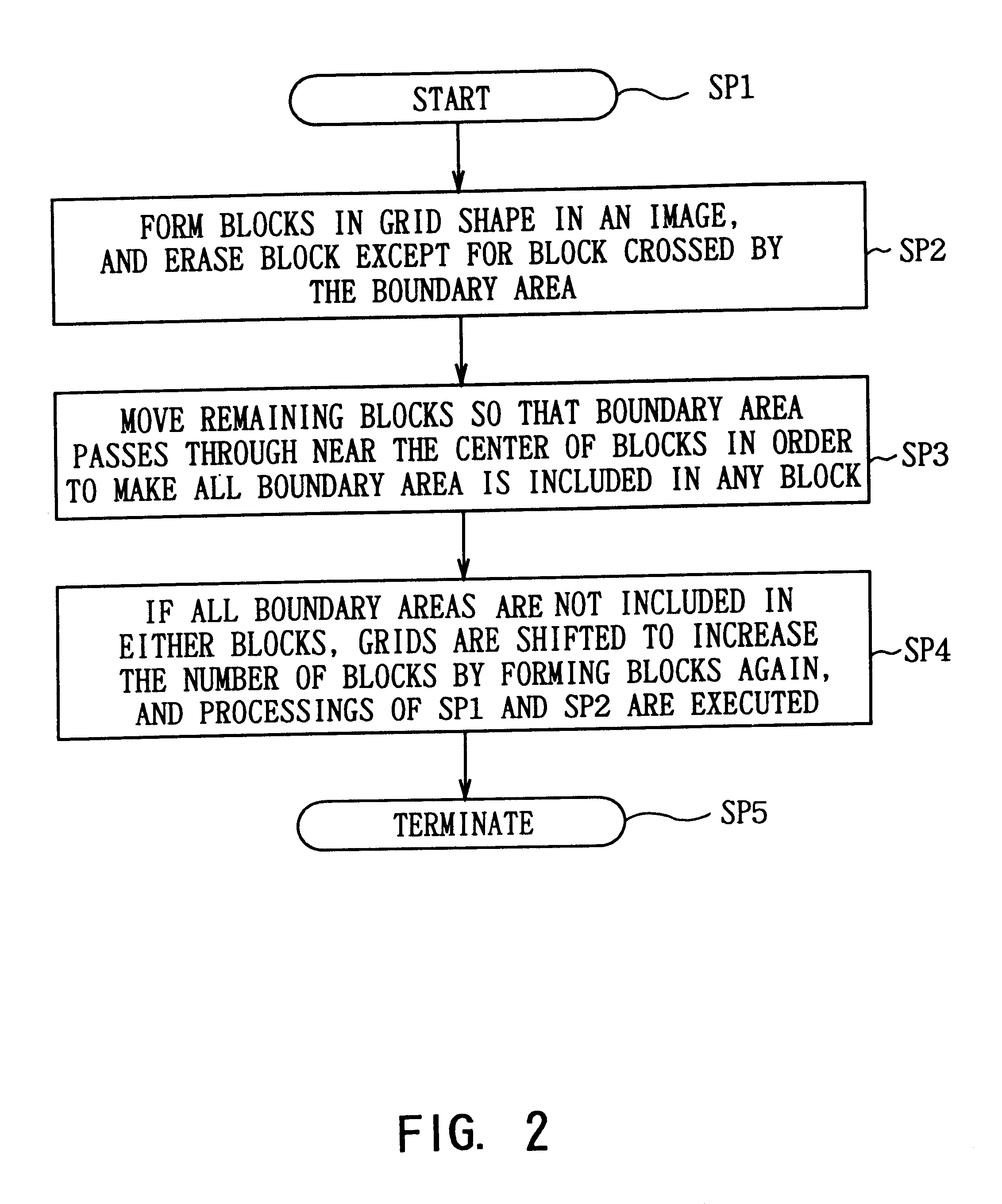
The rough boundary area image in which the boundary area between the desired area and areas other than the desired area is roughly assigned is divided into a plurality of small areas, then the area extracting procedure is executed to each small area to detect the desired area and the areas other than the desired area from each small area, then the boundary area mask image is formed based on the result of above detection, and the desired area is extracted based on the boundary area mask image. Thus, the desired area can be extracted accurately and efficiently from the image.

Problems solved by technology

However, in the chroma key processing and the luminance key processing, an input image of which its characteristics greatly differ according to the position in one screen is processed in accordance with single threshold value to the pixel value of the entire image, the chroma key processing and the luminance key processing cannot be applied to the image with the arbitrary background.
However, since this method is the processing only dependent upon the edge intensity, the correct result cannot be obtained in the area with an intense edge which is not the contour of the object, and there are cases where the accuracy is worse as compared with the video mat method.
Also, in the case where the characteristics of background differs according to the position on the image, since single area extracting method is used, it is impossible to cope with the arbitrary background thoroughly.
However, because the video mat method requires the process to assign the object area per one pixel, it requires much time and skill and there arises a problem that its operational efficiency is not favorable.

Method used


Image

  • Image detecting apparatus
  • Image detecting apparatus
  • Image detecting apparatus

Examples


Embodiment Construction

Preferred embodiments of the present invention will be described with reference to the accompanying drawings:

(1) General Construction

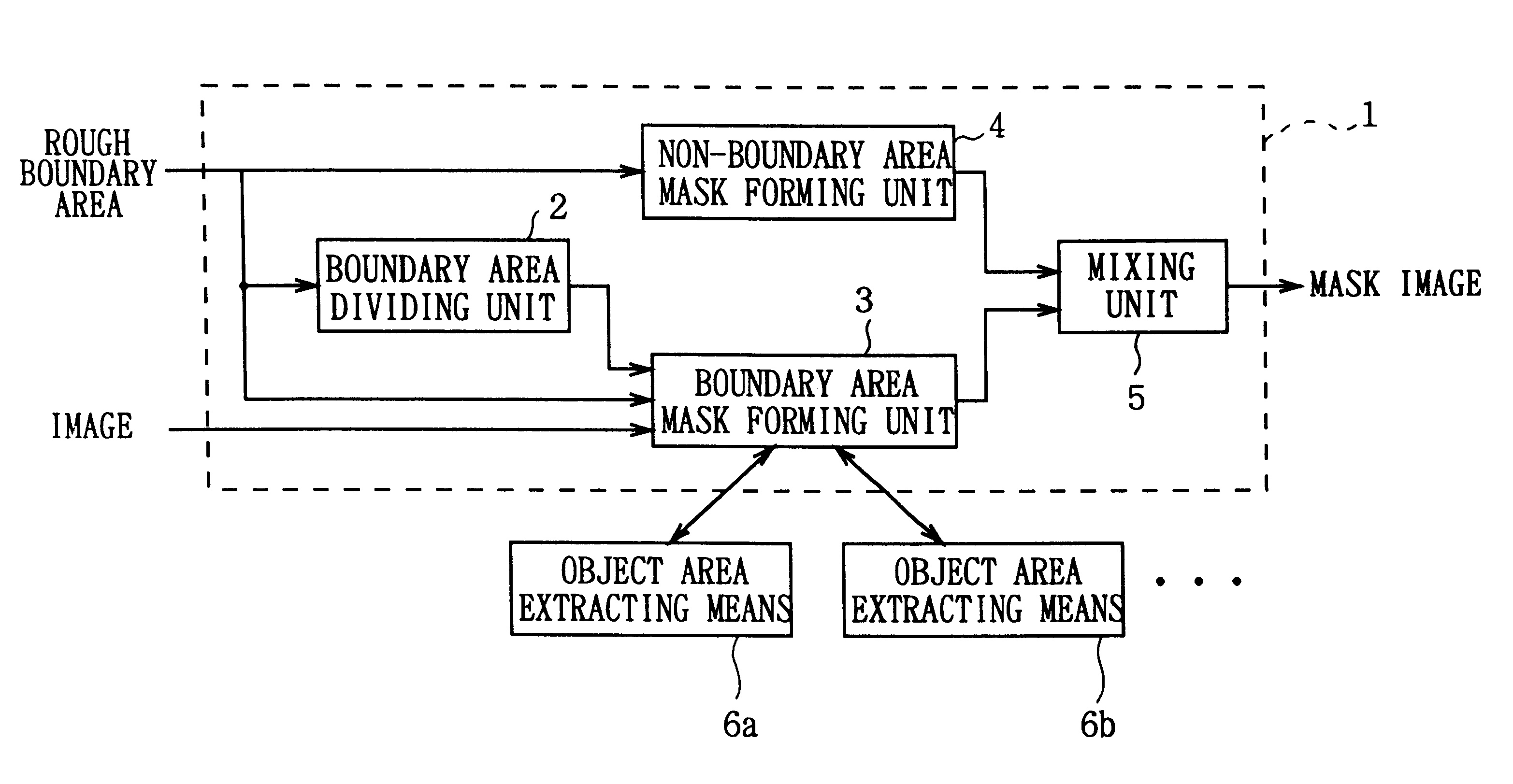
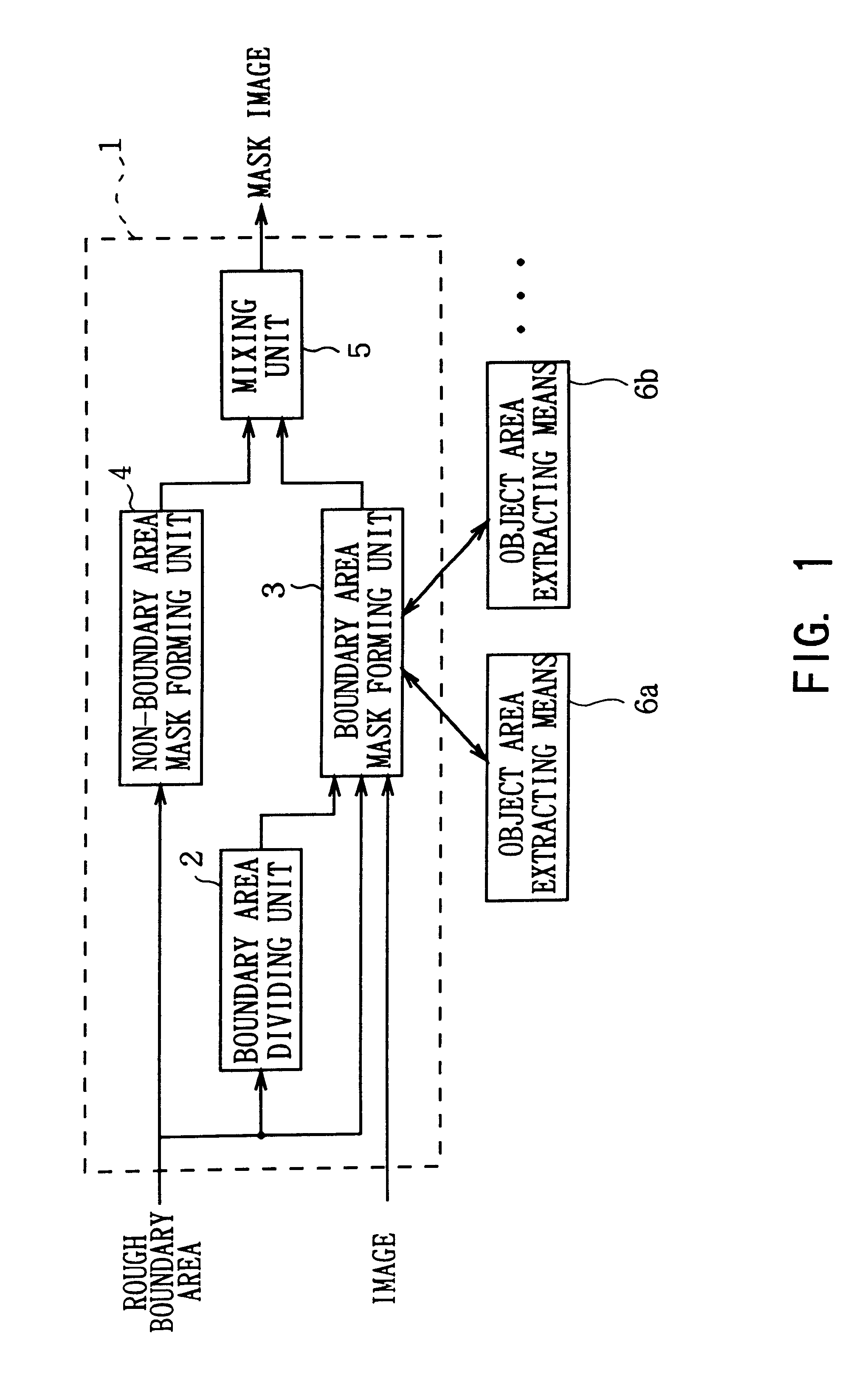
In FIG. 1, 1 generally shows an object area extracting apparatus according to the embodiment of the present invention. As shown in FIG. 1, the object area extracting apparatus 1 consists of a boundary area dividing unit 2, a boundary area mask forming unit 3, a non-boundary area mask forming unit 4 and a synthesizing unit 5. The boundary area mask forming unit 3 is connected to the plural number of object area extracting means 6a, 6b . . . . Each of the object area extracting means respectively have input means, which are not shown.

As shown in FIG. 1, the image including the object desired to be extracted and the rough boundary area image in which the boundary area between the object and the background is roughly assigned are input to the object area extracting apparatus 1. Here, the rough boundary area image is binary mask image. The boundary area div...


PUM


Abstract

An image area extracting method for extracting the desired areas from the image accurately and efficiently. The rough boundary area, in which the boundary area is roughly assigned between the desired area and areas other than the desired area, is divided into a plurality of small areas. The area extracting procedure is executed on each small area and the desired area and areas other than the desired area are detected from each small area. The boundary area mask image is formed based on the detection result and the desired area is extracted based on the boundary area mask image. Thus, the desired area can be extracted from the image accurately and efficiently.

Description

1. Field of the InventionThe present invention relates to an image area extracting method and is suitably applied, for example, to the case of forming a key signal (a mask image) which is necessary at the time of an image synthesizing process among the works related to video production.2. Description of the Related ArtTechniques to extract an object from an image are conventionally well-known as methods for special effects. The techniques to extract an object are the mask image hand painting (video mat) method, the method using chroma key processing and luminance key processing, and the rough contour assigning and thinning (Object Extracting Method for Image Mixing, by Seiki Inoue, The transactions of the Institute of Electronics, Information, and Communication Engineers D-II vol.j74-D-II pages 1411-1418, 1991).The mask image hand painting method, in which an operator assigns an object area by hand painting in utilizing a painting tool such as a tablet, is a method capable of inputt...

Claims


Application Information

Patent Timeline
Patent Type & Authority Patents(United States)
IPC IPC(8): G06T5/00H04N5/262
CPCG06T7/0083G06T7/408G06T2207/10016G06T2207/10024G06T2207/20104G06T7/12G06T7/90
Inventor MITSUNAGA, TOMOOTOTSUKA, TAKASHI
Owner SONY CORP
Learn More