Eureka AIR delivers breakthrough ideas for toughest innovation challenges, trusted by R&D personnel around the world.

Region extraction method and device

a region extraction and region technology, applied in image enhancement, instruments, recognition of medical/anatomical patterns, etc., can solve the problems of repetitive and complicated operation, difficult to precisely approximate the contours of organs using a simple graphic in all cases, and difficult to precisely approximate the contours of organs using a simple graphic. achieve the effect of high accuracy, efficient and accurate image processing, and simple operation

Active Publication Date: 2007-07-19
FUJIFILM HEALTHCARE CORP
View PDF11 Cites 16 Cited by
  • Summary
  • Abstract
  • Description
  • Claims
  • Application Information

AI Technical Summary

Benefits of technology

[0017] By implementing this procedure, the method for extracting a region related to the present invention can determine a contour of a desired region (the first contour) with a simple operation and with high accuracy. Further, a region including the stratified region held between at least the first contour and the second contour can be easily extracted as a specified region.
[0018] As a result, through performing a desired image processing on the specified region by the method for extracting the organ region related to the present invention, it is possible to perform an efficient and accurate image processing in a short period of time. Especially, in the case of obtaining an image of a blood vessel such as a coronary artery running on the cardiac surface region, a clear and satisfactory image can be efficiently obtained by extracting only the surface region of a heart by the present invention.

Problems solved by technology

However, the shapes of organs are generally quite complicated, thus making it difficult to precisely approximate the contours of them using a simple graphic in all cases.
Approximation with a simple graphic will surely cause some errors, and the operation for the approximation would be repetitive and complicated work.
Also, the method being disclosed in Patent Document 1 relates to an elliptical internal region, and it causes a problem in the case of extracting a coronary artery located in the cardiac surface region using MIP (Maximum Intensity Projection) processing, because there are occasions upon attempting MIP processing by specifying the region encompassing the heart including the surface region that the coronary artery becomes invisible due to the high signal region of the cardiac internal region being projected.

Method used


Image

  • Region extraction method and device
  • Region extraction method and device
  • Region extraction method and device

Examples


first embodiment

THE FIRST EMBODIMENT

[0049] Hereinafter, the first embodiment of a device and method for extracting regions related to the present invention will be described referring to the attached drawings.

[0050]FIG. 23 is a block diagram showing a hardware configuration of the whole region-extracting device of which the present invention is applied. This region-extracting device is, for example, for using an X-ray CT image of a heart as a processing object image, specifying the vicinity of the cardiac surface area, and acquiring and displaying the blood vessel pattern running over the surface area. This region-extracting device comprises:

[0051] central processing unit (CPU) 10 for controlling the operation of the respective constituent elements;

[0052] main memory 11 for storing the controlling program of the whole device;

[0053] magnetic disk 12 for storing a plurality of tomographic (image) data and programs;

[0054] display memory 13 for temporarily storing image data for display;

[0055] CR...

second embodiment

THE SECOND EMBODIMENT

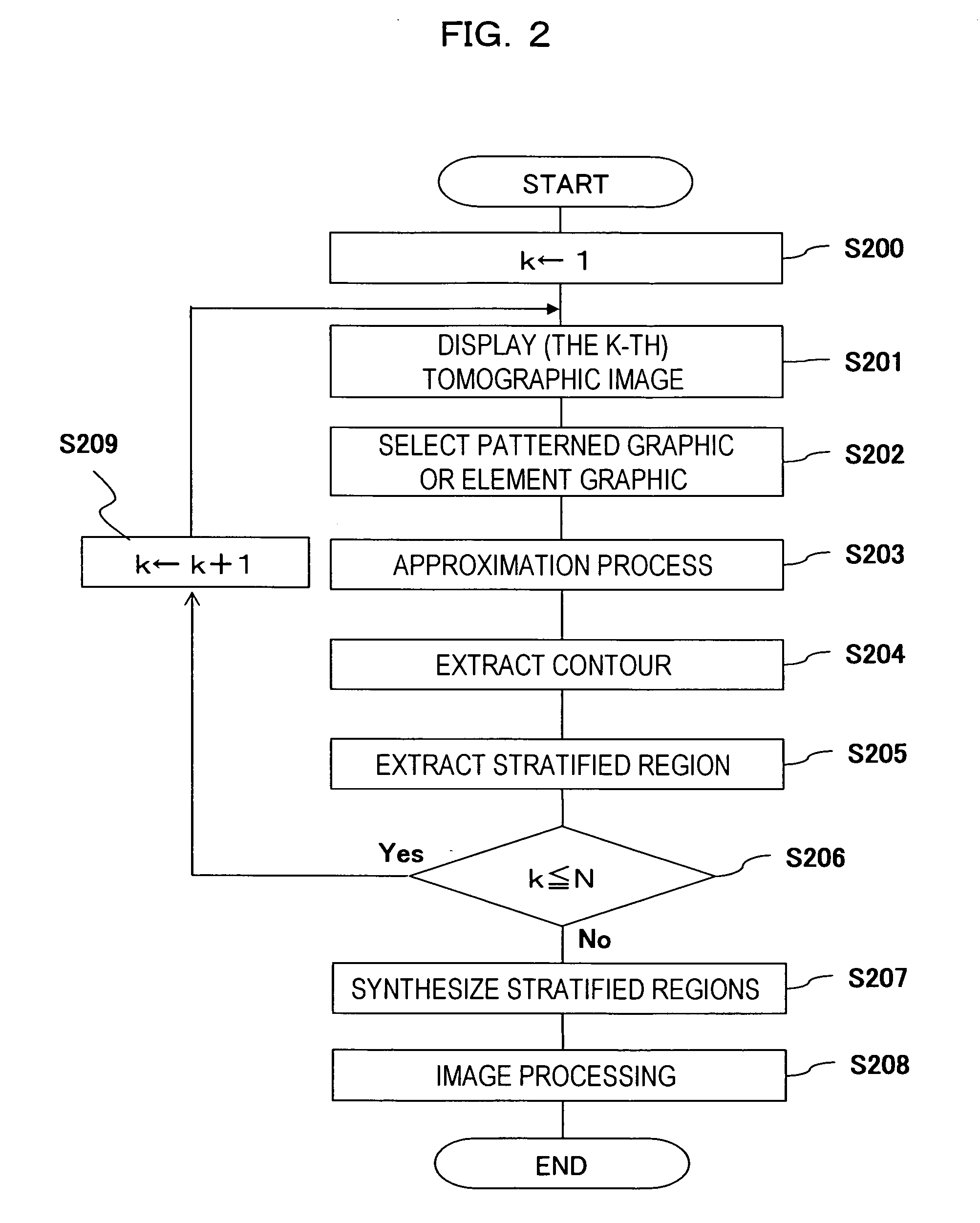
[0088] Next, the second embodiment of the region-extracting device and method related to the present invention will now be described. In this embodiment, a region including at least a stratified region encompassing a desired region is extracted from the respective plural slices of a tomographic image, and the plurality of regions being extracted from the respective tomographic images is synthesized to create a 3-dimensional region. This 3-dimensional region is then specified, and the desired image processing will be performed.

[0089] The description on the configuration of the region-extracting device in the second embodiment will be omitted since it is the same as the one of the first embodiment. Also, an example of the basic operation in the second embodiment will be described based on the flow chart shown in FIG. 2. CPU 10 in FIG. 23 operates according to this flow chart. The procedure for the contour approximation of a desired region in the present embodimen...

third embodiment

THE THIRD EMBODIMENT

[0132] Next, the third embodiment of region-extracting device and method relating to the present invention will be described.

[0133] The present embodiment is for extracting a contour of a desired entire region and the stratified region thereof, by first extracting one or more partial regions being included in a desired region and then combining and synthesizing the respective extracted partial regions. The differences from the previously mentioned second embodiment are that there are no steps S202 and S203 in FIG. 2 because patterned graphics are not used, and the contents of processing in the contour-extracting process in step S204 of FIG. 2 and in the extracting process of stratified regions in step S205. Other than these differences it is the same as the second embodiment. Therefore the present embodiment will be described below focusing on the differences, encoding the parts that are mutually corresponding the second embodiment the same.

[0134] The descripti...


PUM


Abstract

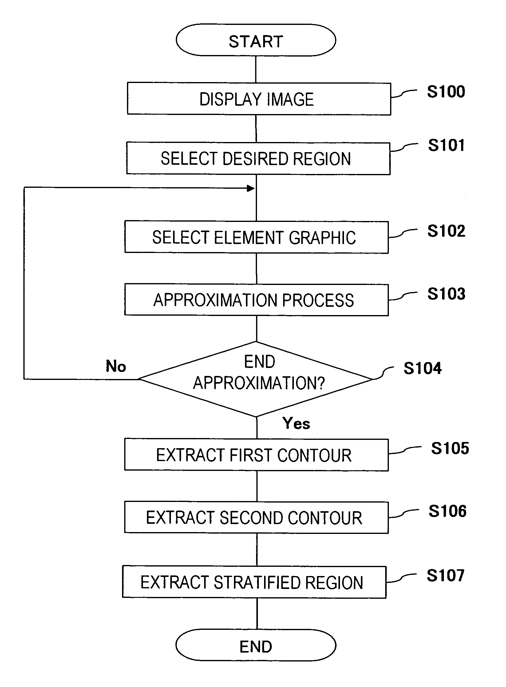
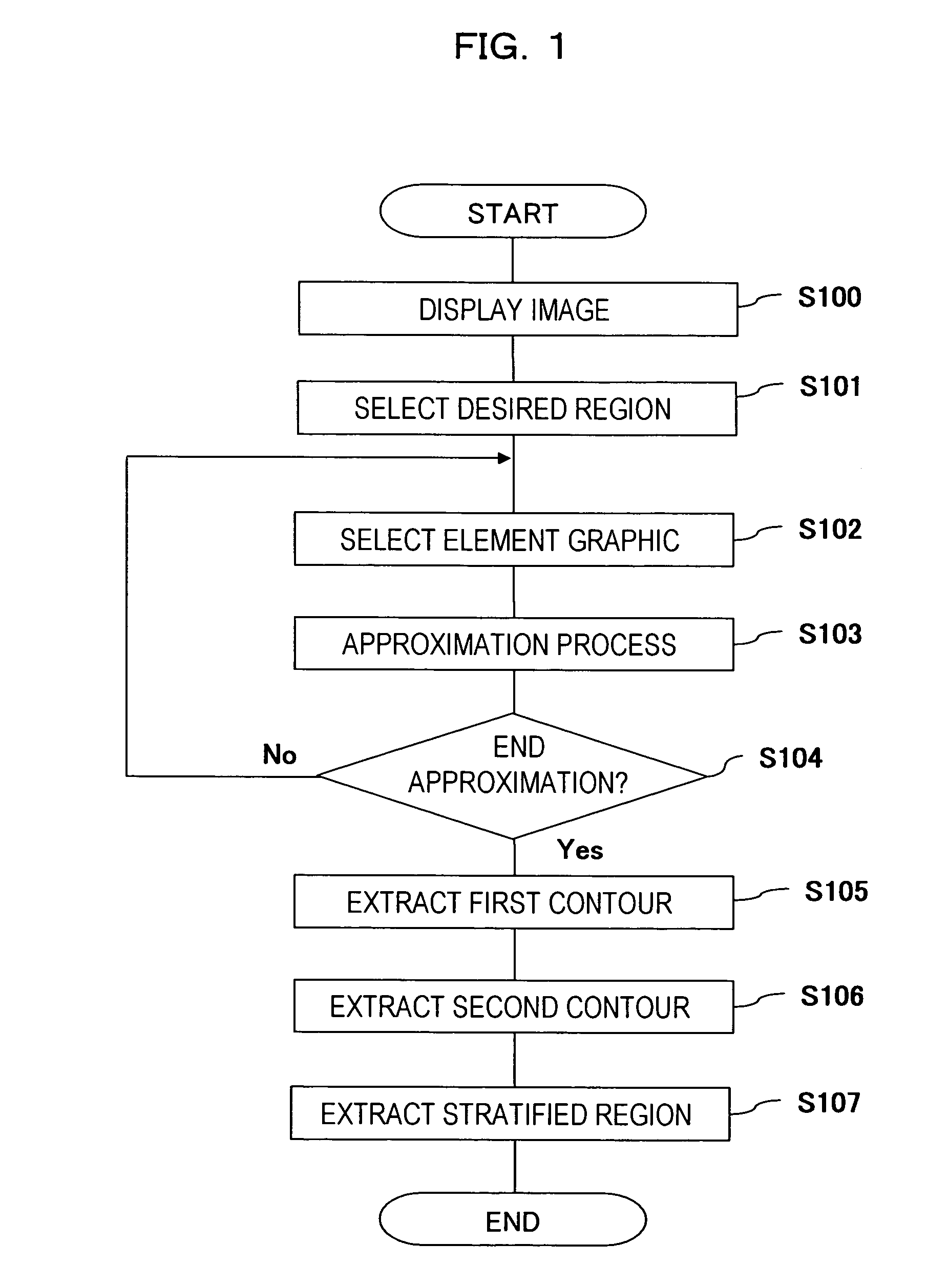
A region-extraction method for extracting a contour of a desired region is provided. The method includes: a step (a) for displaying an image; a step (b) for selecting a desired region in the image; a step (c) for selecting an element graphic corresponding at least a partial contour in a partial region in the desired region; a step (d) for approximating the contour of a part of the element image to at least a partial contour in the partial region; a step (e) for repeating the steps (c) to (d) at least twice; and a step (f) for making a first contour by combining at least a part of elements after the approximation.

Description

TECHNICAL FIELD [0001] The present invention relates to a method and a device for extracting a specified region in an image, and in particular to a technique for extracting a region to which a desired image processing is to be applied. BACKGROUND ART [0002] In recent years, images being obtained with image diagnostic apparatuses such as X-ray, X-ray CT or MRI have been widely used, not only at the time of diagnosis, but also at the time of treatment. There has especially been an increase in studies for extracting automatically a specified organ out of display images for the purpose of diagnosis or treatment. For example, displaying the coronary artery pattern running in the vicinity of cardiac surface in 3-dimensional representation would be extremely useful at clinical sites. [0003] However, in the case of segmenting the organ regions or extracting the specified regions, there is still a need for doctors to rely on their anatomical knowledge for diagnosis and recognition. Particula...

Claims


Application Information

Patent Timeline
Patent Type & Authority Applications(United States)
IPC IPC(8): G06K9/48A61B6/03G06T5/00G06V10/26
CPCG06K9/34G06K9/4638G06K2209/05G06T2207/30048G06T7/0089G06T2207/10081G06T2207/20116G06T7/0083G06T7/12G06T7/149G06V10/26G06V10/457G06V2201/03
Inventor GOTO, YOSHIHIRO
Owner FUJIFILM HEALTHCARE CORP
Why Eureka
Eureka Blog
Learn More