Fluid-dispensing valve for a container-filling apparatus

a technology for container-filling apparatus and fluid-dispensing valve, which is applied in liquid handling, packaging goods, transportation and packaging, etc., can solve the problems of compromising sterility and rapid growth of bacteria in such fluid-deposited deposits, and achieve the effect of improving sealing efficiency and improving the secureness of the valve elements against axial separation

Inactive Publication Date: 2001-07-03
FILLER SPECIALTIES
View PDF22 Cites 21 Cited by
  • Summary
  • Abstract
  • Description
  • Claims
  • Application Information

AI Technical Summary

Benefits of technology

According to a further feature of this invention, a non-compressible, annular contact surface is axially superimposed on an inward surface of each annular shoulder of the biasing member, the annular contact surfaces each receivable within the circumferential groove of one of said clamps. Such contact surface may take the form of a metal or plastic annulus, for instance a ring or washer. The annulus provides a contact surface receivable within the annular channel of the clamp, thereby improving securement of the valve elements against axial separation.
According to still a further feature, the fluid-dispensing valve includes sealing means provided between abutting axial mating surfaces to improve sealing efficiency in the assembled valve. According to one feature of this invention, these sealing means comprise a raised annular member provided on one of a pair of abutting axial mating surfaces, and an annular groove provided on the other of said pair of abutting axial mating surfaces, wherein said raised annular member is receivable in said annular groove in sealing engagement.

Problems solved by technology

Because fluids are communicated through the valves during dispensing, the various valve components are inevitably exposed to, and become covered with, the dispensed fluid.
Without such routine maintenance, bacteria would rapidly thrive in such fluid deposits and compromise sterility.

Method used


Image

  • Fluid-dispensing valve for a container-filling apparatus
  • Fluid-dispensing valve for a container-filling apparatus
  • Fluid-dispensing valve for a container-filling apparatus

Examples


Embodiment Construction

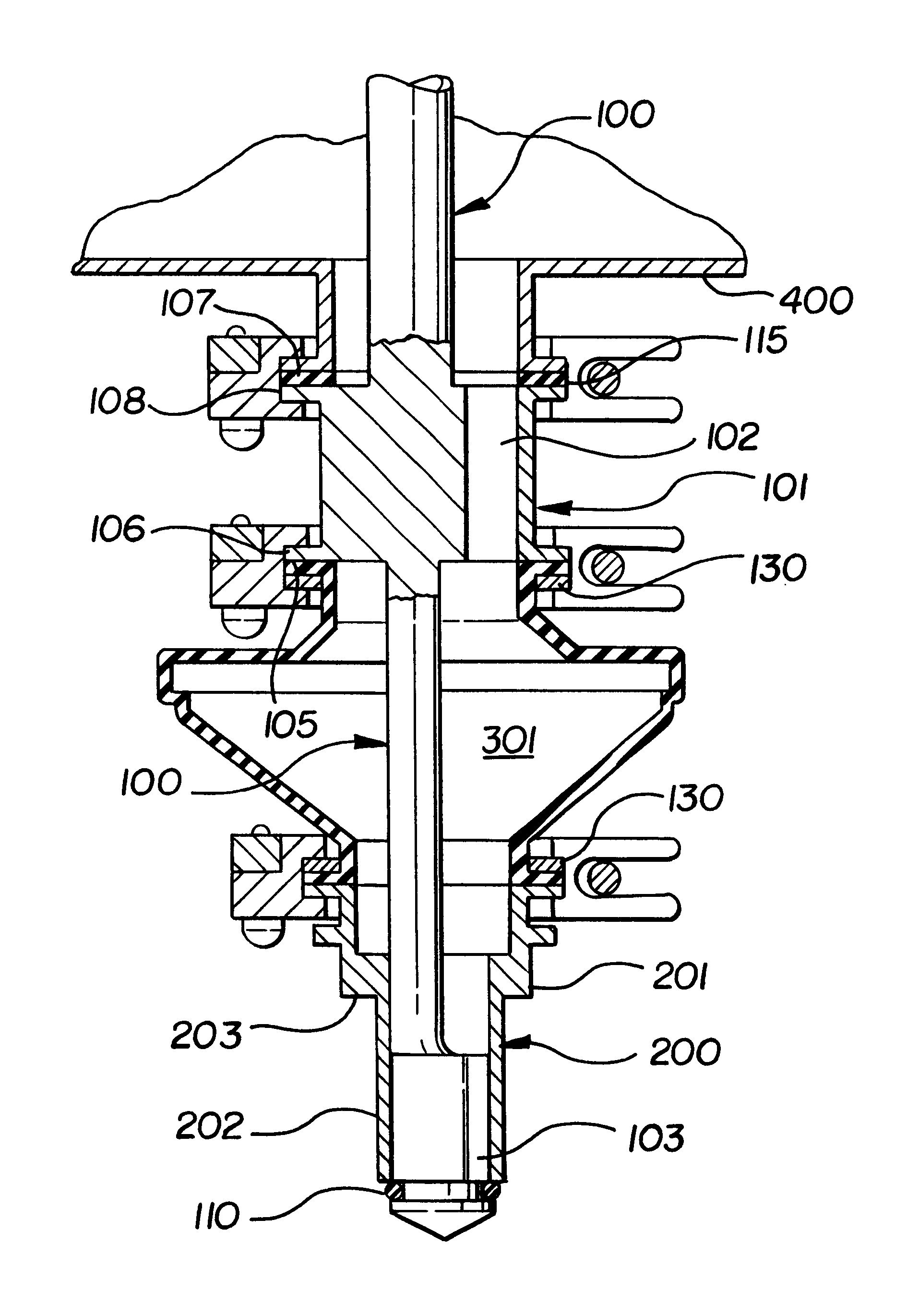
Referring now to the drawings, wherein like numerals indicate like or corresponding parts, the present invention will be better understood. The present invention most generally comprises a fluid-dispensing valve, having application in conjunction with fluid-dispensing apparatus, for instance automated bottling apparatus. The present inventive valve is particularly well-suited, though not limited in application, to beverage or other fluid dispensing where sterility is a concern since, as explained further below, the inventive valve reduces contamination of valve components and facilitates valve cleaning, as compared to prior art valves.

Referring to FIG. 5, the inventive valve comprises most generally a vent tube 100 and a nozzle 200 moveably interrelated by a biasing member, such as the illustrated bellows or diaphragm 300.

Vent tube 100 is generally of a construction known in the art for fluid-dispensing valves of the operational type described herein. Exemplary construction of a ven...


PUM

PropertyMeasurementUnit
dimensionsaaaaaaaaaa
movementaaaaaaaaaa
frictionaaaaaaaaaa

Abstract

A fluid-dispensing valve for a container-filling apparatus comprises a vent tube having an axial mating surface; a nozzle positionable over and axially moveable in relation to the vent tube to define open and closed conditions of the fluid-dispensing valve, the nozzle including an axial mating surface; a biasing member for biasing the nozzle in a closed condition of the fluid-dispensing valve, the biasing member having a fluid passageway therethrough, and further including at least two axial mating surfaces, one axial mating surface axially abutting with an axial mating surface of each of the vent tube and nozzle to define an axially mated condition of the fluid-dispensing valve; and one or more members for maintaining the vent tube, nozzle, and biasing member in the axially mated condition of the fluid-dispensing valve.

Description

The present invention pertains to container-filling apparatus, such as are employed for automatically filling containers with fluids, including consumables such as juice and dairy products. More particularly, the present invention concerns an improved fluid-dispensing valve for such container-filling apparatus, the valve being characterized by reduced assembled contact between the several fluid-contacting components thereof so as to minimize valve contamination by fluids dispensed through the valve.Automated fluid container-filling apparatus have long been known, and provide efficient and economical means for the mass packaging of various consumer goods, including bottled beverages such as juice and milk.In the container-filling industry, one common automated container-filling apparatus is the rotary or turret type machine, which operates to precisely fill a series of bottles from a common fluid supply via a plurality of valves.Conventional turret-type container-filling apparatus mo...

Claims


Application Information

Patent Timeline
Patent Type & Authority Patents(United States)
IPC IPC(8): B65B39/00
CPCB65B39/004
Inventor SLAGH, BRUCE
Owner FILLER SPECIALTIES
Why Eureka
Try Eureka