Process for fabricating plastic optical fiber

a technology of plastic optical fiber and manufacturing process, which is applied in the direction of cladding optical fiber, instruments, other domestic articles, etc., can solve the problems of insignificant use of optical fiber, inconvenient installation, and inability to meet the requirements of cladding, so as to achieve gradual transition into the cladding region and narrow the width of the core region

Inactive Publication Date: 2001-07-03
FITEL USA CORP
View PDF9 Cites 20 Cited by
  • Summary
  • Abstract
  • Description
  • Claims
  • Application Information

AI Technical Summary

Benefits of technology

Conditions: T.sub.oper =300.degree. C., R.sub.0 =0.25 cm, R.sub.core /R.sub.0 =0.35 (Q.sub.core /Q.sub.total =0.273), Q.sub.total =0.0707 cm.sup.3 /sec.
The value of Q.sub.total for this Example corresponds to making 300 micron diameter fiber at a production speed of 1 m/s or 250 micron diameter fiber at a speed of 1.4 m/s. As the core and cladding materials progress through the diffusion zone, the diffusion front separating these materials widens, indicating diffusion of the dopant into the cladding region. To illustrate this effect and to show the role of diffusion zone length in the extent of dopant diffusion, the dopant mass-fraction field is plotted as a function of normalized radius in FIG. 6A at different axial locations, z, within the diffusion zone. As the dopant material progresses through the diffusion zone, the profile diffuses away from the step-index profile at the inlet and towards a more smoothly varying profile. The profile at a distance of 100 cm into the diffusion zone exhibits significantly more diffusion of the dopant into the cladding region than at 50 cm.
To illustrate the effect of rearrangement of the flow at the diffusion-zone exit (i.e., at the exit die) on the final dopant mass-fraction profile, the mapped p

Problems solved by technology

Such optical fiber has not found significant usage, however, in smaller scale applications, such as distribution of fiber to the desk in local area networks.
In particular, glass optical fiber has not been as cost effective as, for example, copper wire, and also requires extremely precise fiber connections.
Unfortunately, the modes traveling along a step index fiber experienced an undesirably high level of dispersion, thereby limiting the fiber's capability.
GI-POF, however, was more difficult, and thus more expensive, to manufacture than step-index POF.
Extrusion was expected to be quicker and cheaper than forming and drawing a preform, but the need for a graded refractive index profile created complications.
In particular, it is not clear that the process is able to be performed without providing a delay time (stopping the flow of material) or a very slow extrusion spe

Method used


Image

  • Process for fabricating plastic optical fiber
  • Process for fabricating plastic optical fiber
  • Process for fabricating plastic optical fiber

Examples


example 2

te

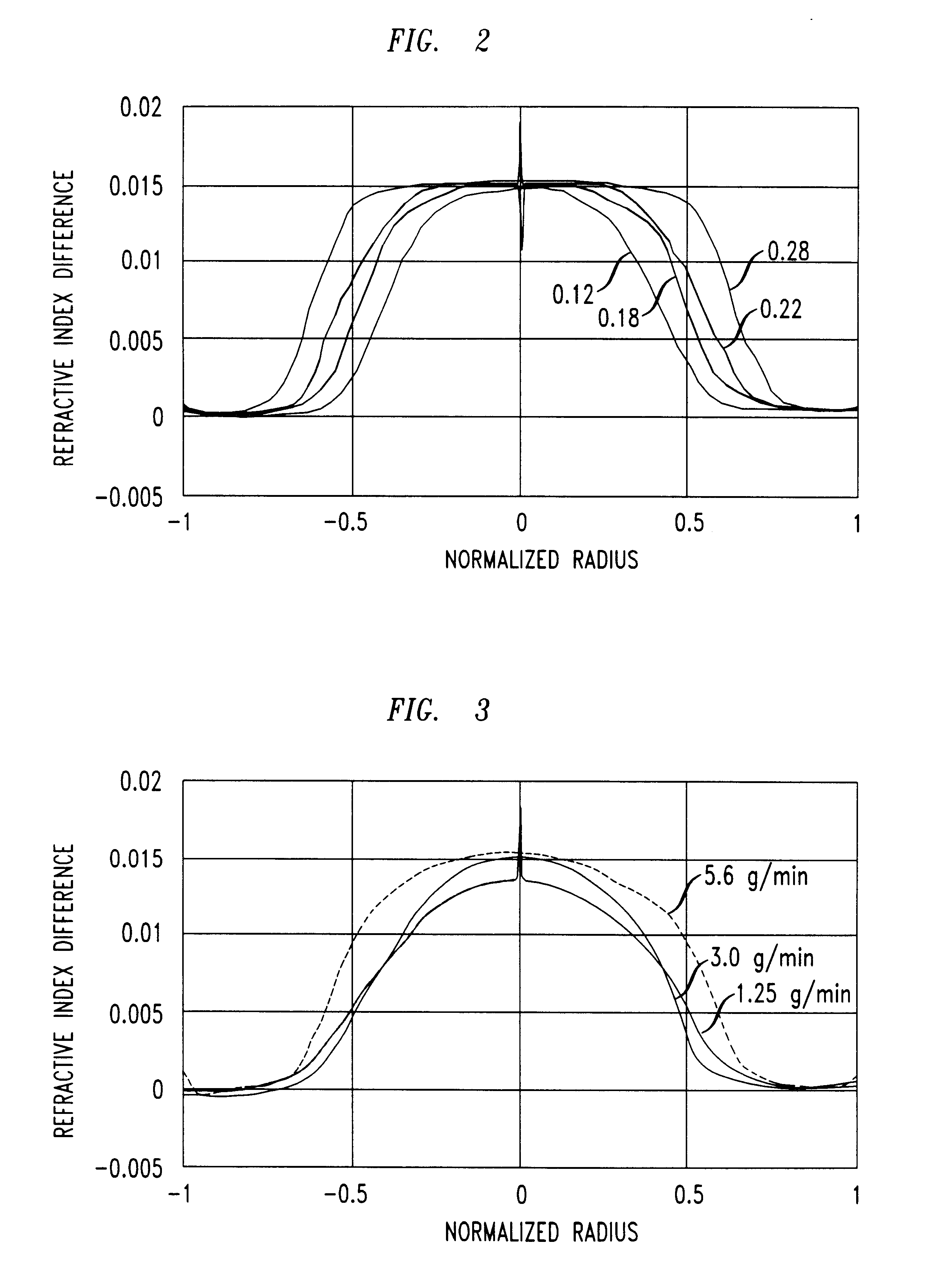
Another experiment was performed to determine the effect of output rate on the refractive index profile, keeping the diffusion zone length, the diffusion zone temperature and the core / cladding extruder rpm ratio constant. In this experiment the diffusion zone length was one meter, the diffusion zone temperature 250.degree. C. and the core / cladding extruder rpm ratio approximately 0.2. In all cases the temperature profile on the core extruder was set to deliver melt to the co-extrusion crosshead at 190.degree. C., while the profile on the cladding extruder was set to deliver material at 220.degree. C. The co-extrusion crosshead was set at 220.degree. C.

For the first fiber the core extruder rpm was 0.75, the cladding extruder rpm was 3.75 and the total output was 1.25 grams per minute. For the second fiber the core extruder rpm was 1.5, the cladding extruder rpm was 7.5 and the total output was 3.0 grams per minute. For the third fiber the core extruder rpm was 4.0 and the cladding ...

example 3

Zone Length

An experiment was performed to determine the effect of diffusion zone length on the profile of the GI-POF. For this experiment the co-extrusion crosshead temperature was set at 220.degree. C., the core extruder rpm at 1.5 and the cladding extruder rpm at 7.5. The diffusion zone temperature was set to 230.degree. C. for all lengths. For the first run the diffusion zone length was 0.67 meters. The fiber was drawn directly from the end of the diffusion section without using an exit die. Half of the diffusion section was then removed, leaving a diffusion zone length of 0.33 meters. A second fiber was drawn from this diffusion zone length. Finally the entire diffusion section was removed and a fiber was drawn directly from the co-extrusion crosshead.

As shown in FIG. 4, comparison of the three profiles shows that as the diffusion zone length is increased the refractive index gradient at the boundary between the core and cladding is reduced and made more gradual owing to the dif...

example 4

Zone Temperature

An experiment was performed to determine the effect of diffusion zone temperature on the profile of the GI-POF. The crosshead temperature was set at 220.degree. C. The temperature of the core melt entering the crosshead was set at 190.degree. C. The temperature of the cladding material entering the crosshead was 220.degree. C. For all runs the diffusion zone length was one meter, the output rate was approximately 6 grams / minute and the ratio of the core to cladding extruder screw rpm was held at 0.32 for all runs.

In the first run, the diffusion zone temperature was set at 230.degree. C., the cladding extruder rpm was 10.6 and the core extruder rpm was 3.4 which resulted in an output rate of 6.2 grams per minute. In the second run the diffusion zone temperature was set at 270.degree. C., and the individual core and cladding extruder rpm's were set at 3.2 and 10, respectively, keeping the ratio at 0.32 with an output of 5.9 grams / minute.

As shown in FIG. 5, the profile ...


PUM

PropertyMeasurementUnit
Lengthaaaaaaaaaa
Lengthaaaaaaaaaa
Lengthaaaaaaaaaa

Abstract

A continuous extrusion process is provided capable of producing graded index plastic optical fiber at commercially useful speeds, e.g., at least 1 m/sec for 250 mum outer diameter fiber. Moreover, it is possible to predict the refractive index profile of the fiber, prior to actual fabrication, by performing a finite element analysis using various parameters of the extrusion process. Such prediction allows one to tune the parameters of the process to obtain a desirable outcome, while avoiding the need for substantial trial and error with the extrusion equipment.

Description

1. Field of the InventionThe invention relates to fabrication of graded-index plastic optical fiber.2. Discussion of the Related ArtGlass optical fiber has become a significant transmission medium in recent years, particularly for long distance transmission applications. Such optical fiber has not found significant usage, however, in smaller scale applications, such as distribution of fiber to the desk in local area networks. In particular, glass optical fiber has not been as cost effective as, for example, copper wire, and also requires extremely precise fiber connections. There has been interest, therefore, in pursuing plastic optical fiber (POF), which offers many of the benefits of glass optical fiber, but is expected to be more cost effective. POF also offers a larger core, which makes connection and splicing easier.Initially, step index POF (having a core of one refractive index, surrounded by a cladding of a different refractive index) was manufactured and used. Unfortunately...

Claims


Application Information

Patent Timeline
IPC IPC(8): B29C47/06B29D11/00B29C47/00G02B6/00B29C48/05B29C48/30G02B6/028
CPCB29C47/0014B29D11/00682B29C47/128B29C47/00B29L2011/0075B29C48/05B29C48/00B29C48/304G02B6/00
Inventor BLYLER, JR., LEE L.HART, JR., ARTHUR CLIFFORDSALAMON, TODD R.VIRIYAYUTHAKORN, MONTRI
Owner FITEL USA CORP
Why Eureka
Try Eureka