Imaging compositions and methods

a composition and composition technology, applied in the field of compositions and methods, can solve the problems of no means suitable for use demanding real time processing, screen printing also meets with difficulty in obtaining fine patterns with precision, and cannot achieve the effect of stabilizing the color or shade change, rapid and efficient, and slowing down the tedious process of applying marks

Inactive Publication Date: 2006-12-05
ROHM & HAAS ELECTRONICS MATERIALS LLC
View PDF113 Cites 25 Cited by
  • Summary
  • Abstract
  • Description
  • Claims
  • Application Information

AI Technical Summary

Benefits of technology

[0015]In a further embodiment the imaging compositions include one or more micro-encapsulated antioxidants. The antioxidants stabilize the color or shade change when they are released from their capsules.
[0018]In yet a further embodiment a method comprises providing an imaging composition comprising one or more sensitizers in sufficient amounts to affect a color or shade change in the composition upon exposure to energy at intensities of 5 mW or less, one or more micro-encapsulated antioxidants and one or more color formers; applying the imaging composition to a work piece; applying energy to the imaging composition at the intensities of 5 mW or less to affect the color or shade change; stabilizing the color or shade change; executing a task on the work piece as directed by the color or shade change to modify the work piece; and peeling the composition from the work piece.
[0019]The color or shade change may be used in the manufacture or repair of work pieces to alter the initial color or shade of a work piece, or to vary the color or shade of a work piece upon exposure to suitable energy levels. The imaging compositions and methods provide a rapid and efficient means of changing the color or shade of a work piece or of placing an image on a work piece such as aeronautical ships, marine vessels and terrestrial vehicles, or for forming images on textiles.
[0020]The image may be used as a mark or indicator, for example, to drill holes for fasteners to join parts together, to form an outline for making a logo or picture on an airplane, or to align segments of marine vessel parts. Since the compositions may be promptly applied to the work piece and the image promptly formed by application of energy at intensities of 5 mW or less to create a color or shade contrast, workers no longer need to be adjacent the work piece to mark laser beam images with a hand-held marker or tape in the fabrication of articles. Accordingly, the problems of blocking light caused by the movement of workers hands and the slower and tedious process of applying marks by workers using a hand-held marker or tape is eliminated. Further, the low intensities of energy, which are used to cause the color or shade change, eliminates or at least reduces the potential for ophthalmological damage to workers.
[0021]The reduction of human error increases the accuracy of marking. This is important when the marks are used to direct the alignment of parts such as in aeronautical ships, marine vessels or terrestrial vehicles where accuracy in fabrication is critical to the reliable and safe operation of the machine.
[0022]The imaging compositions may be applied to the substrate by methods such as spray coating, brushing, roller coating, ink jetting, dipping or other suitable methods. Energy sources for applying a sufficient amount of energy to create the color or shade change include, but are not limited to, laser, infrared and ultraviolet light generating apparatus. Conventional apparatus may be employed, thus new and specialized apparatus are not necessary to use the compositions and methods. Additionally, the single, non-selective coating application of the compositions on the work piece followed by prompt application of energy to create the color or shade change makes the compositions suitable for assembly line use. Also, the compositions may be peeled from the work piece avoiding the use of undesirable solvents or developers. Such solvents and developers may be carcinogenic and potentially contaminate the environment thus, costly waste treatment is used to reduce environmental pollution. Accordingly, the compositions provide for more efficient manufacturing than many conventional alignment and imaging processes, and also reduce the amount of waste treatment.

Problems solved by technology

Pad printing has an advantage in printing on a curved surface because of the elasticity of the pad but is disadvantageous in making a fine pattern with precision.
Screen printing also meets with difficulty in obtaining a fine pattern with precision due to the limited mesh size of the screen.
Besides the poor precision, since printing involves making a plate for every desired pattern or requires time for setting printing conditions, these methods are by no means suitable for uses demanding real time processing.
Unless the specification is strictly met, the ink sometimes causes obstruction of nozzles, resulting in an increase of reject rate.
There are, however, certain disadvantages associated with state-of-the art laser marking techniques that burn the surface to achieve a desired mark.
Further, oils or other contaminants deposited on the article surface subsequent to marking may blur or even obscure the laser mark.
Additionally, because the laser actually burns the surface of the work piece, for bare die marking, the associated burning may damage any underlying structures or internal circuitry or by increasing internal die temperature beyond acceptable limits.
Moreover, where the manufactured part is not produced of a laser reactive material, a laser reactive coating applied to the surface of a component adds expense and may take hours to cure.
Such methods are tedious, and the workers' hands may block the laser image disrupting the alignment beam to the work piece.
Another problem associated with laser marking is the potential for ophthalmological damage to the workers.
Many lasers used in marking may cause retinal damage to workers.
Generally, lasers, which generate energy exceeding 5 mW present hazards to workers.

Method used


Image

  • Imaging compositions and methods
  • Imaging compositions and methods
  • Imaging compositions and methods

Examples


example 1

Phototropic Imaging Composition

[0099]The phototropic imaging composition with components disclosed in the table below are prepared at room temperature under red light.

[0100]

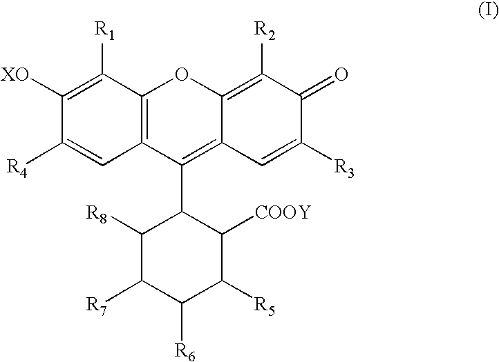
TABLE 1ComponentPercent WeightFilm forming acrylic polymer25Calcium carbonate20o-chloro-hexaarylbiimidazole62′,4′, 5′,7′-tetrabromo-0.53,4,5,6-tetrachlorofluoresceindisodium salt2,2-methylene-bis(4-methyl-6-0.5tertbutylphenol)Leuco Crystal Violet1Polyalky betaine polysiloxane copolymer2Ethylene glycol phenyl ether10Water35

[0101]The acrylic polymer is a latex polymer which may be prepared by known methods in the art, or may be obtained commercially from Rohm and Haas Company of Philidelphia, Pa. under the tradename RHOPLEX™ E-1801. The polyalkyl betaine polysiloxane copolymer is mixed with the acrylic polymer in water to form an aqueous suspension. Calcium carbonate is added to the aqueous suspension to provide a pH of from 8 to 11.

[0102]Leuco crystal violet, O-chloro-hexaarylbiimidazole, 2′,4′,5′,7′-tetrabromo-3,...

example 2

Photofugitive Composition

[0107]The components listed in the table below are combined to at room temperature under red light to form a photofugitive imaging composition.

[0108]

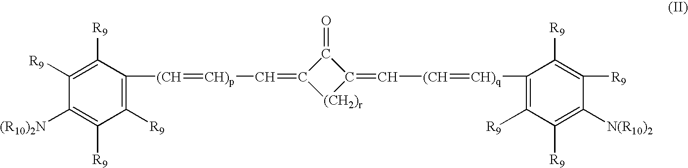
TABLE 2ComponentsWeight PercentCopolymer of styrene and acrylic acid25Calcium carbonate20Cyclopentanone-2,5-bis [[4-0.5(diethylamino)phenyl]methylene]-Leuco Crystal Violet1o-chloro-hexaarylbiimidazole6.51,2-naphthoquinone0.5Triethanolamine triacetate1.5Polyalkyl betaine polysiloxane copolymer2Ester alcohol8Water35

[0109]Copolymers of styrene and acrylic acid are known and methods for preparing them may be found in the literature. They are also commercially available such as under the tradename RHOPLEX™ P-376, which is obtainable from Rohm and Haas Company. The copolymer is mixed in water with the polyalkyl betaine polysiloxane copolymer to form an aqueous suspension. Calcium carbonate is added to the suspension to maintain a pH of 8 to 11.

[0110]The imaging components: leuco crystal violet, o-chloro-hexaarylbiimid...

example 3

Phototropic Composition

[0114]The following composition is prepared at room temperature under red light.

[0115]

TABLE 3ComponentWeight PercentVinyl acetate / acrylic copolymer emulsion252-alkyl-2-imidazoline15Vinyl aromatic polymer5Leuco Crystal Violet1Tribromo methyl phenyl sulfone6.52′,4′, 5′, 7′-tetraiodo-0.53,4,5,6-tetrachlorofluoresceindisodium salt2,2′-methylene-bis(4-methyl-26-tertbutylphenol)Ethylene glycol phenyl ether10Water35

[0116]The vinyl acetate / acrylic copolymer is known in the art and methods of preparing it are well known. Such copolymers also are commercially available under the trade-name ROVACE™ 661, which is obtainable from Rohm and Haas Company. The copolymer, vinyl aromatic polymer, and the 2-alky-2-imidazoline are mixed in water to form an aqueous emulsion.

[0117]The imaging components: leuco crystal violet, tribromo methyl phenyl sulfone, 2′,4′,5′,7′-tetraiodo-3,4,5,6-tetrachlorofluorescein disodium salt, and micro-encapsulated 2,2′-methylene-bis(4-methyl-6-tertbu...


PUM

PropertyMeasurementUnit
isoelectric pointaaaaaaaaaa
Tgaaaaaaaaaa

Abstract

Imaging compositions and methods of using the compositions are disclosed. The imaging compositions are sensitive to low levels of energy such that upon application of the low levels of energy the compositions change color or shade. The compositions may be applied to a work piece to mark it and removed from the work piece by peeling.

Description

[0001]The Patent application is a continuation-in-part of co-pending patent application Ser. Nos. 10 / 773,989, 10 / 773,990, and 10 / 773,991 filed Feb. 6, 2004.BACKGROUND OF THE INVENTION[0002]The present invention is directed to imaging compositions and methods where the imaging compositions undergo a color or shade change upon exposure to energy at low intensities. More specifically, the present invention is directed to imaging compositions and methods where the imaging compositions undergo a color or shade change upon exposure to energy at low intensities and may be peeled from workpieces on which they are coated.[0003]There are numerous compositions and methods employed in various industries to form images on substrates to mark the substrates. Such industries include the paper industry, packaging industry, paint industry, medical industry, dental industry, electronics industry, textile industry, aeronautical, marine and automotive industries, and the visual arts, to name a few. Imag...

Claims


Application Information

Patent Timeline
Patent Type & Authority Patents(United States)
IPC IPC(8): G03C1/73G03F7/031G03F7/032G03F7/20G03F7/42B41M5/28B25H7/00B41M5/26B41M5/30B41M5/46
CPCG03C1/73Y10S430/163Y10S430/127G03C1/732B41M5/26
Inventor BARR, ROBERT K.O'CONNOR, COREY
Owner ROHM & HAAS ELECTRONICS MATERIALS LLC
Why Eureka
Try Eureka