Method and apparatus for performing current shaping for seeking acoustics reduction in a disk drive

a disk drive and current shaping technology, applied in the field of disk drive current shaping, can solve the problems of many disk drives failing to meet acceptable noise levels during seek operations, affecting the integrity of data stored on the disk drive, and customer perception of the disk drive operating in a faulty manner

Inactive Publication Date: 2001-07-03
MAXTOR
View PDF15 Cites 48 Cited by
  • Summary
  • Abstract
  • Description
  • Claims
  • Application Information

AI Technical Summary

Problems solved by technology

When the performance of a disk drive is not at an acceptable level, customer dissatisfaction regarding the disk drive may be significant, and the integrity of data stored on the disk drive may be compromised.
By way of example, when a disk drive experiences excessive vibration, a customer may perceive the disk drive to be operating in a faulty manner.
Additional seeking acoustics are typically the result of disk drive structural vibration induced by the seek current.
However, as overall seeking acoustics are often in the range of approximately 45 dB to approximately 50 dB, many disk drives fail to meet acceptable levels of noise during seek operations.
Failure to meet acceptable levels for overall seeking acoustics may lead to disqualification of disk drives by customers, as well as performance issues related to the disk drives.
Specifically, a higher level of noise is generally attributed to a more rapid change in a current level.
However, although the use of a foam damping layer is effective to reduce overall seeking acoustics, the use of a foam damping layer reduces overall seeking acoustics by no more than approximately 2 dB.
Further, the use of a foam damping layer is expensive, as it is an additional part that is added to a disk drive, and also requires additional manufacturing time to mount the foam damping layer on the disk drive.
As such, the use of a foam damping layer is often not desirable, since the costs associated with the foam damping layer are relatively high given the reduction of overall seeking acoustics that is possible using the foam damping layer.
However, foam damping layers are often still used to at least slightly reduce overall seeking acoustics.
As was the case with using a foam damping layer, the rubber pieces also do not significantly reduce overall seeking acoustics.
In addition, the use of rubber pieces is expensive due to the fact that the cost associated with creating the rubber pieces, as well as the time associated with accurately positioning the rubber pieces between the VCM and the top cover, is significant with respect to the reduction of overall acoustics attributed to the use of the rubber pieces.
Therefore, the use of rubber pieces to absorb energy may be considered to be a less than desirable solution to the problem of reducing the overall seeking acoustics in a disk drive.
Further, the use of notch filters often increases the seek time associated with performing a seek.
However, input shaper techniques are not readily adaptable for use in disk drive technology.
That is, modifying input shaper techniques for use in disk drive systems is often complicated, since servo code associated with disk drive systems is arranged to perform a phase-plane seek, as will be appreciated by those skilled in the art, while input shaper techniques are time-based.
As reconfiguring input shaper techniques to perform a phase-plane seek may be complicated and time-consuming, and only selected resonant modes are rendered unexcitable, i.e., the overall seeking acoustics may not necessarily be reduced to an acceptable level, the use of such current shaping techniques in disk drive systems may not be desirable.
A larger variation in velocity error results in a larger variation in command current, and is a source of acoustic noise.
For example, the disk drive head may never accurately reach its desired location, e.g., the on-track performance of the overall disk drive may be unacceptable.
As accuracy is crucial and shorter seek times are more efficient than longer seek times, a relatively long seek time is often considered to be undesirable

Method used


Image

  • Method and apparatus for performing current shaping for seeking acoustics reduction in a disk drive
  • Method and apparatus for performing current shaping for seeking acoustics reduction in a disk drive
  • Method and apparatus for performing current shaping for seeking acoustics reduction in a disk drive

Examples


Embodiment Construction

The present invention will now be described in detail with reference to a few preferred embodiments thereof as illustrated in the accompanying drawings. In the following description, numerous specific details are set forth in order to provide a thorough understanding of the present invention. It will be obvious, however, to one skilled in the art, that the present invention may be practiced without some or all of these specific details. In other instances, well known structures and process steps have not been described in detail in order not to unnecessarily obscure the present invention.

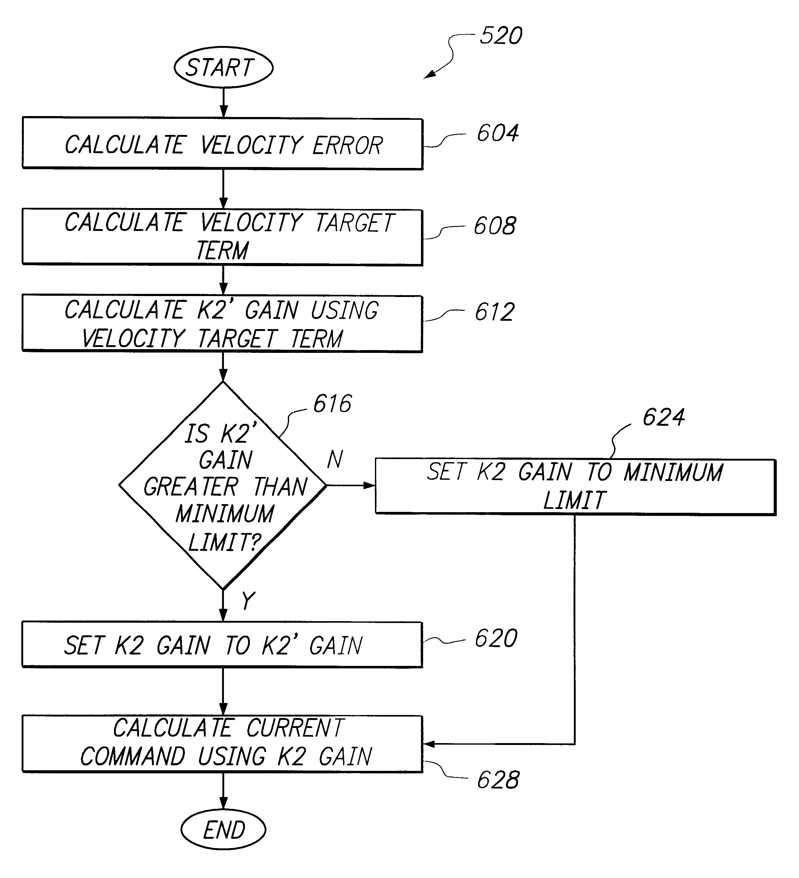
In accordance with one embodiment of the present invention, a current command is used to effectively shape the deceleration portion of a seek current such that additional seeking acoustics associated with the deceleration portion may be reduced. Specifically, a current command, e.g., a shaping command, is arranged to produce a seek current that reduces oscillatory characteristics in a seek trajector...


PUM

PropertyMeasurementUnit
frequencyaaaaaaaaaa
velocity erroraaaaaaaaaa
currentaaaaaaaaaa

Abstract

Methods and apparatus for reducing overall seeking acoustics in a head-disk apparatus are disclosed. In accordance with one aspect of the present invention, a method for reducing overall seeking acoustics in a disk drive apparatus, which includes an actuator, involves calculating an error that is a measure of a difference between a desired trajectory for the actuator and an actual trajectory for the actuator, and calculating a preliminary gain. The method also includes determining when the preliminary gain exceeds a minimum acceptable gain limit, and updating a current command using the preliminary gain and the velocity error when the preliminary gain exceeds the minimum acceptable gain limit. The preliminary gain is generally arranged to enable the updated current command to reduce the overall seeking acoustics. The updated current command is sent to a power amplifier which then generates a seek current signal using the power amplifier and the updated current command. The updated current command allows the actual trajectory to substantially follow the desired trajectory.

Description

1. Field of InventionThe present invention relates generally to methods and apparatus for use in disk drives for computer systems. More particularly, the present invention relates to methods and apparatus for reducing the vibration of high frequency resonance modes associated with seeking acoustics in disk drives for computer systems.2. Description of the Relevant ArtThe reduction of noise, or vibrations, in disk drives is crucial to ensure that performance issues associated with a disk drive may be minimized. When the performance of a disk drive is not at an acceptable level, customer dissatisfaction regarding the disk drive may be significant, and the integrity of data stored on the disk drive may be compromised. By way of example, when a disk drive experiences excessive vibration, a customer may perceive the disk drive to be operating in a faulty manner. Therefore, the magnitude of the vibrations experienced on a disk drive must generally be reduced to acceptable levels.FIG. 1 is...

Claims


Application Information

Patent Timeline
Patent Type & Authority Patents(United States)
IPC IPC(8): G11B5/55
CPCG11B5/5547
Inventor SCHMIDT, THORSTENWANG, JWO-MIN
Owner MAXTOR
Why Eureka
Try Eureka