Air drag reducing apparatus

a technology of air drag and reducing apparatus, which is applied in the direction of vehicle body streamlining, monocoque construction, vehicle body, etc., can solve the problems of air drag, poor visibility, turbulence and drag,

Inactive Publication Date: 2001-07-10
TRANSTEX LLC
View PDF4 Cites 185 Cited by
  • Summary
  • Abstract
  • Description
  • Claims
  • Application Information

AI Technical Summary

Benefits of technology

More specifically, this is achieved by providing an apparatus which allows the panels to be moved outwardly from a drag reducing position to a position where the doors are in their fully retracted position adjacent their associated sides of the vehicle.
A further object of the present invention is to provide a mechanism which will enable the panels to return back to their drag reducing position whenever the doors are hingedly moved from their retracted position to their end closing position. This is achieved by providing a pressure exerting element which assists the panel to return to its drag reducing position.

Problems solved by technology

It is known that a significant amount of air drag results when a vehicle travels over a roadway; this is due to an area of low pressure created at the rear end of the vehicle.
For example, with a tractor-trailer type vehicle, the air makes a sharp bend around the squared-off back of the trailer, thus causing turbulence and drag.
Furthermore, the turbulence also causes poor visibility in rainy conditions and an accumulation of dirt on the back of trailers.
Therefore, the addition of aerodynamic device, such as a rear defector, diminishes the air drag and results in lower fuel consumption.
However, in this drag apparatus, the ram construction does not enable the doors to be moved between a closed position to a completely opened position where the doors are adjacently parallel to the sides of the trailer vehicle.

Method used


Image

  • Air drag reducing apparatus
  • Air drag reducing apparatus
  • Air drag reducing apparatus

Examples


first embodiment

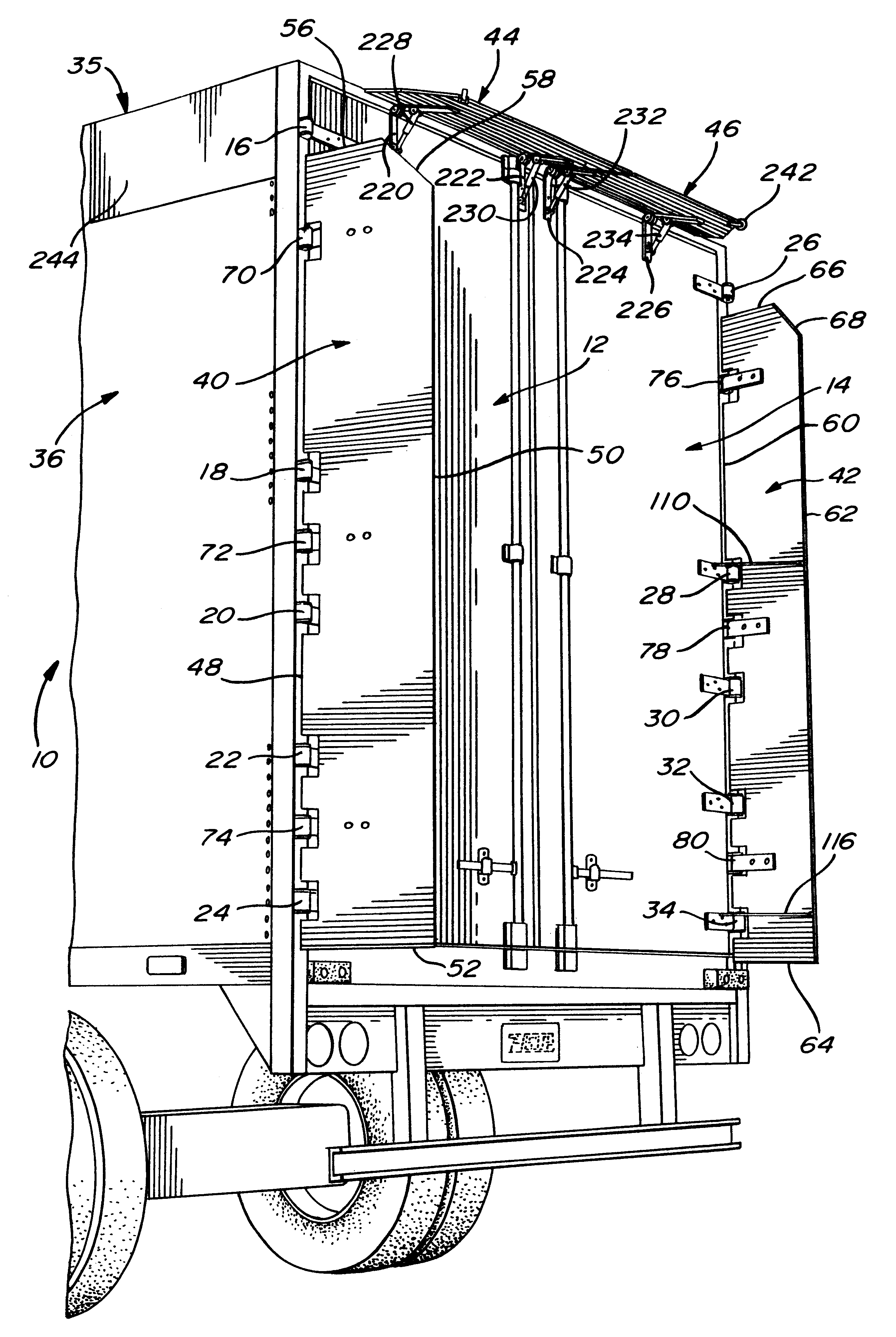
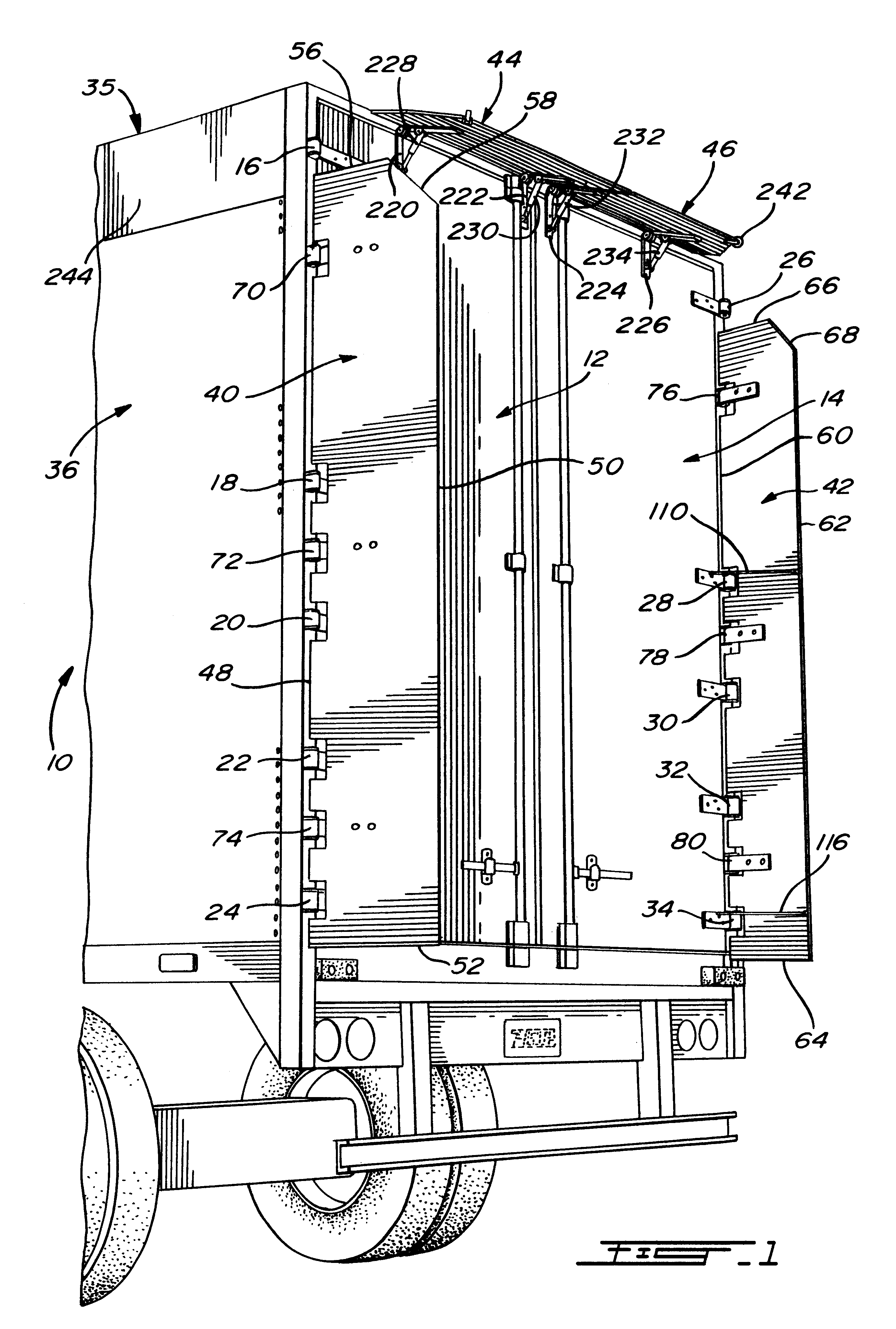
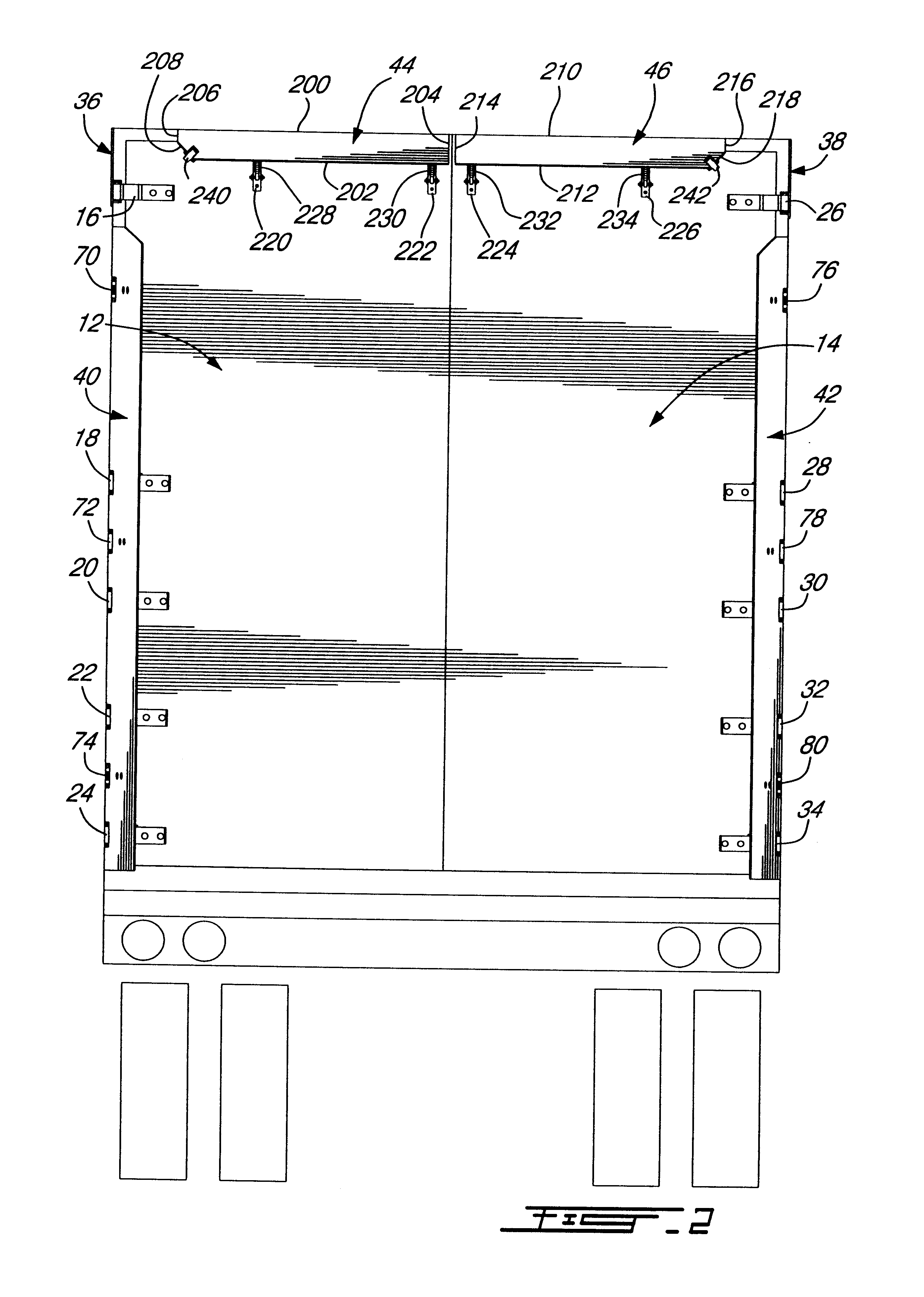
the air drag reducing apparatus of the present invention will be described with respect to the side panels 40 and 42. It should be understood, however, that both panels are equipped with the same elements for positioning them in the desired angle degree; therefore, a description will only be given for panel 40 since its application to the other panel 42 is identical.

Referring to FIGS. 3, 4 and 5, the means for positioning panel 40 in its preferred drag reducing position, consists of a pair of coil springs 102 and 104 mounted at hinges 70 and 74. If needed, a third coil spring could be mounted at hinge 72; however, it has been found that a pair of coil springs is sufficient to achieve the air drag reducing portion of the panel.

As detailed in FIG. 6, the coil spring 102 has one end 106 contacting the inner wall of panel 40 and the opposite 108 contacting the hinge bracket 109. This spring is tensioned so that the spring end 106 will force the panel 40 by the pressure of the hinge into...


PUM


Abstract

An air drag reducing apparatus for use with a vehicle having a rear end closed by a pair of doors consists of a rectangular shaped panel having a leading edge hingedly connected to the vehicle, the panel extending at about 15 degrees relative to the rearward projection of a side of the vehicle. An element positions the panel in a drag reducing position; this element is such that it allows the panel to be moved between the door and the side of the vehicle as the door is opened and moved to a position adjacent the side of the vehicle. As the door is moved back from the opened position to a closed position, the element causes the panel to return to its drag reducing position. The rear of a vehicle may include two side panels with or without two top panels.

Description

The present invention relates to an air drag reducing apparatus for use with vehicles having a rectangular rear end closed by a pair of hingedly mounted doors.It is known that a significant amount of air drag results when a vehicle travels over a roadway; this is due to an area of low pressure created at the rear end of the vehicle. For example, with a tractor-trailer type vehicle, the air makes a sharp bend around the squared-off back of the trailer, thus causing turbulence and drag. To overcome this problem, engine power is required and therefore fuel. Furthermore, the turbulence also causes poor visibility in rainy conditions and an accumulation of dirt on the back of trailers.In the trucking industry, the aerodynamics of vehicles is a growing concern. Tests indicate that fuel savings from aerodynamic improvements are equivalent to fuel savings attained by a chassis weight reduction and require fewer services to maintain. The air resistance or aerodynamic drag of the vehicle incr...

Claims


Application Information

Patent Timeline
Patent Type & Authority Patents(United States)
IPC IPC(8): B62D35/00
CPCB62D35/001
Inventor BOIVIN, MATHIEUROBERGE, KARIC
Owner TRANSTEX LLC
Why Eureka
Try Eureka