Pipette dispensing block

a pipette and dispensing technology, applied in the field of pipette dispensing blocks, can solve the problems of difficult access to individual pistons, time-consuming, and daunting replacement of one or several hollow tube pistons, and achieve the effect of improving seals, resilient and lasting longer

Inactive Publication Date: 2001-07-10
SS8 NETWORKS
View PDF22 Cites 81 Cited by
  • Summary
  • Abstract
  • Description
  • Claims
  • Application Information

AI Technical Summary

Benefits of technology

It is an object of the present invention to provide a better seal for pipette pistons in a pipette dispensing block.
It is another object of the present invention to provide easily engagable and disengagable engaging means by which pipette piston heads may be associated and attached to a lifting plate.
It is another object of the present invention to provide a more resilient and longer lasting vacuum seal between a pipette piston and its head block.

Problems solved by technology

As the hollow tube piston 50 forms one of ninety-six (96) such hollow tube pistons in an 8.times.12 array of such pistons, it becomes a daunting, time-consuming, and tedious task to replace one or several of the hollow tube pistons 50.
The retaining rings 54, 56 consequently limit the utility of the Astle '302 patent device by making access to individual pistons more difficult.
Consequently, it can be seen that the use of retaining rings (such as those indicated by reference numbers 54 and 56, and the Astle '302 patent) creates some drawbacks with respect to the useful life and easy repair of pipette systems such as that shown in the Astle '302 patent.

Method used


Image

  • Pipette dispensing block
  • Pipette dispensing block
  • Pipette dispensing block

Examples


Embodiment Construction

)

The detailed description set forth below in connection with the appended drawings is intended as a description of presently preferred embodiments of the invention and is not intended to represent the only forms in which the present invention may be constructed, used, and / or utilized. The description herein sets forth the functions and the sequence of steps for constructing and operating the invention in connection with the illustrated embodiments. However, it is to be understood that the same or equivalent funtions and sequences may be accomplished by different embodiments that are also intended to be encompassed within the spirit and scope of the invention.

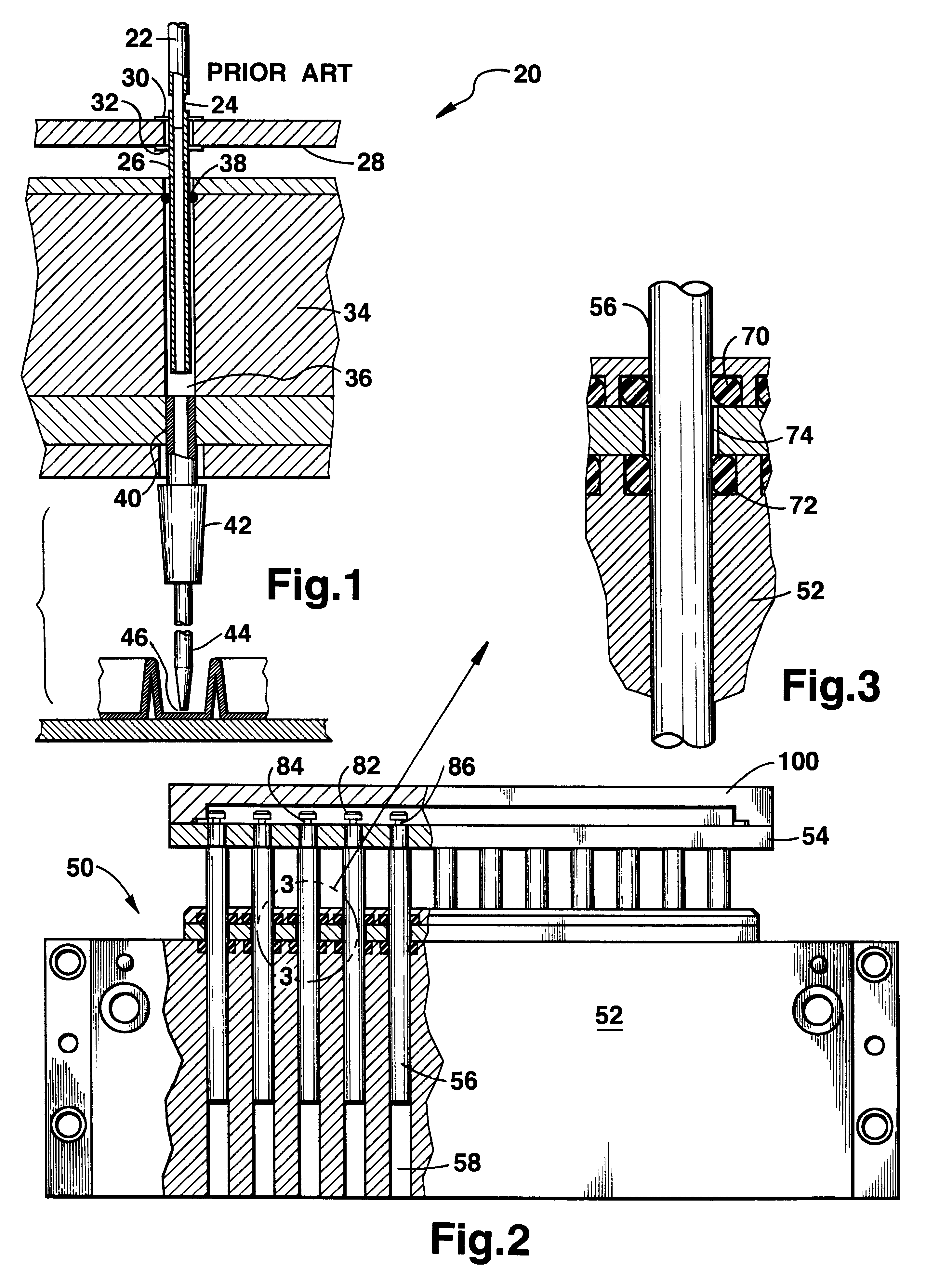
The shortcomings in the prior art are illustrated by FIG. 1 which corresponds in significant portion to FIG. 5 of the U.S. Pat. No. 5,525,302 issued to Astle on Jun. 11, 1996 (the "Astle '302 patent"). In FIG. 1, the Astle '302 patent pipette dispensing apparatus 20 is shown.

In FIG. 1, a flexible tube 22 leads into a hollow tran...


PUM

PropertyMeasurementUnit
vapor pressureaaaaaaaaaa
heightaaaaaaaaaa
volumesaaaaaaaaaa

Abstract

A pipette dispensing block has an improved piston seal and lift plate engagement/disengagement means. In a pipette dispensing block where a piston is used to create a pressure differential to aspirate or extract and dispense or eject fluid material, the maintenance of a vacuum or increased pressure is enhanced by a pair of O-ring seals engaging the piston. A reservoir separates the O-rings and is filled with a low vapor pressure lubricant such as silicone oil or grease. The lubricant is maintained in the reservoir by the O-rings and serves to enhance the vacuum seal while maintaining the O-rings in a pliable and resilient manner. The heads of the pistons are engraved or grooved to leave a circular central pillar surrounded above and below by the piston head and a lower intermediate piston pillar section. The individual pistons are arranged in straight rows so that a slat may slip through opposite pairs of opposing piston pillars thereby entrapping the pistons and preventing them from sliding past the lift plate as the lift plate is lifted upwardly. Shoulders present on the pistons below the lift plate serve to allow the lift plate to push the pistons into the cylindrical chambers of the head block so that a pipette dispenser is provided. The lift plate or portions thereof are then trapped between the slats and the piston shoulders, coupling the pistons to the lift plate. Upward and downward control is thereby established and maintained by the lift plate on the pistons.

Description

1. Field of the InventionThis invention relates to laboratory equipment, and more particularly to a pipette dispensing block used in biologically-related laboratories that aspirates and dispenses fluid volumes in a precise and controlled manner.2. Description of the Related ArtRecently, biology has increasingly incorporated elements of basic molecular and atomic chemistry, yielding the field of biotechnology. The secrets nature has hidden in mammalian and other biology are increasingly being unraveled and discovered. With greater knowledge of molecular biochemistry, genefic structure and effect, coupled with the ability to reproduce biologically active molecules quickly and easily, a corresponding increase in research has demanded tools and equipment that are able to promote the investigative activities related to present day biotechnology.U.S. Pat. No. 5,525,302 issued Jun. 11, 1996 to Astle for a Method and Device for Simultaneously Transferring Plural Samples sets forth machinery...

Claims


Application Information

Patent Timeline
Patent Type & Authority Patents(United States)
IPC IPC(8): B01L3/02G01N35/10
CPCB01L3/02B01L3/022G01N35/1065B01L2400/0487B01L2300/0829
Inventor YIU, FELIX H.
Owner SS8 NETWORKS
Why Eureka
Try Eureka