
Meshing method and apparatus

a technology of meshing and apparatus, applied in the field of meshing methods, can solve the problems of difficult automatic generation, labor-intensive and time-consuming methods, and few practical methods for automatically generating quadrilateral meshes

Inactive Publication Date: 2001-07-10
IBM CORP
View PDF1 Cites 28 Cited by
  • Summary
  • Abstract
  • Description
  • Claims
  • Application Information

AI Technical Summary

Benefits of technology

Another object of the present invention is to provide a meshing method for generating a quadrilateral mesh having less distortion.
A further object of the present invention is to provide a hexahedral mesh generation method which enables mesh generation performed in two dimensions to be performed in three dimensions.
It is still another object of the present invention to provide a quadrilateral mesh generation method that can be employed for a complicated geometric model.
In the present invention, to implement a bubble alignment that is similar to the molecular alignment in the metallic bond, the potential field that represents an effect of an inter-bubble force is assumed. That is, the inter-bubble force is not always directed toward the centers of the adjacent bubbles, but can be directed toward points that are near the centers, so that inter-bubble force is calculated for a state wherein the bubbles are not in a close-packed hexagonal structure. For the generation of a quadrilateral mesh and a hexahedral mesh, in the present invention, four or six adjacent points at which the potential is the lowest are located in each bubble, and the attractive force for adjacent bubbles acts to bring them to the adjacent points. This makes the processing simple.

Problems solved by technology

Hei 8-315183, there are very few practical methods for automatically generating a quadrilateral mesh.
Therefore, in generating a quadrilateral mesh, many analysts rely on a method that is labor-intensive and time-consuming (e.g., several months) to acquire the CAD data for one vehicle.
As described above, although there is a large demand for an automatic quadrilateral mesh generation method, not only is automatic generation difficult to achieve, but also the following procedural constituents must be considered.
According to an analysis performed using computational dynamics, an extremely long element or an element having an extremely large (or small) angle adversely affects the analysis result.
However, when the size of the mesh elements is suddenly changed, the T-structure (e.g., the state in which the nodal points of adjacent elements lie on a chord) occurs, and adversely affects the analysis.
However, providing a quadrilateral mesh (hexahedral mesh) to be used for a three-dimensional model is still seldom done.
Pairing for linking triangles is difficult, and one triangle will remain unlinked if the number of triangles is not even.
It is difficult to generate a quadrilateral that is anisotropic.
With either of the above methods problems are encountered in automatic quadrilateral generation with regard to the direction, and currently, merely a heuristic rule is employed in the phase devoted to resolving these problems.
Additionally, the method proposed for changing a triangular mesh into a quadrilateral mesh is not very practical, even though the expansion into a three-dimensional mesh is theoretically possible.
When a mesh is to be generated for all the parts of a vehicle, the job will be enormous.
However, since the elements inside the region tend to be deformed, requirement (1) is not satisfied.
Additionally, since the direction in which the elements are aligned is limited to the direction along the boundary of the regions, requirement (2) is not satisfied.
With this method, since the quality of the mesh around the boundaries may be very low and this tends to adversely affect the accuracy of the analysis, requirement (1) is not satisfied.
Additionally, since control of the element size is difficult, requirement (3) is not satisfied.

Method used


Image

  • Meshing method and apparatus
  • Meshing method and apparatus
  • Meshing method and apparatus

Examples


Embodiment Construction

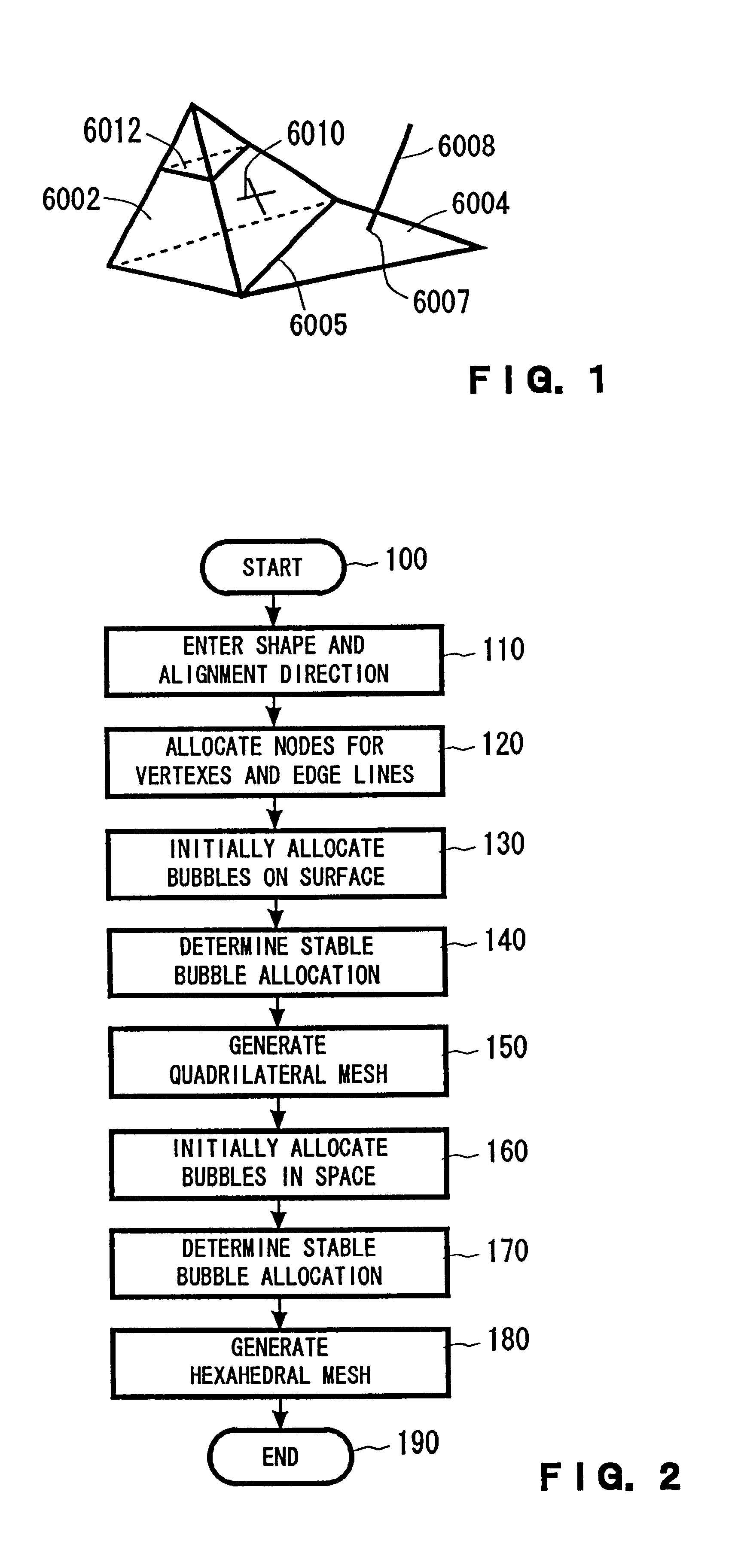
Preferred embodiments of the present invention will now be described by using an example of meshing for a non-manifold data structure. FIG. 1 shows an example object represented by a non-manifold data structure.

In the object in FIG. 1, a triangle 6004, which is a two-dimensional object, contacts a tetrahedron 6002, which is a three-dimensional object, along an edge line 6005, which is a boundary. A line 6008, which is a one-dimensional object, contacts the triangle 6004 at a point 6007 that is shared. A"",which is a one-dimensional object, is attached to one of the sides of the tetrahedron 6002. Additionally, the tetrahedron 6002 is divided by an internally divided boundary line 6012.

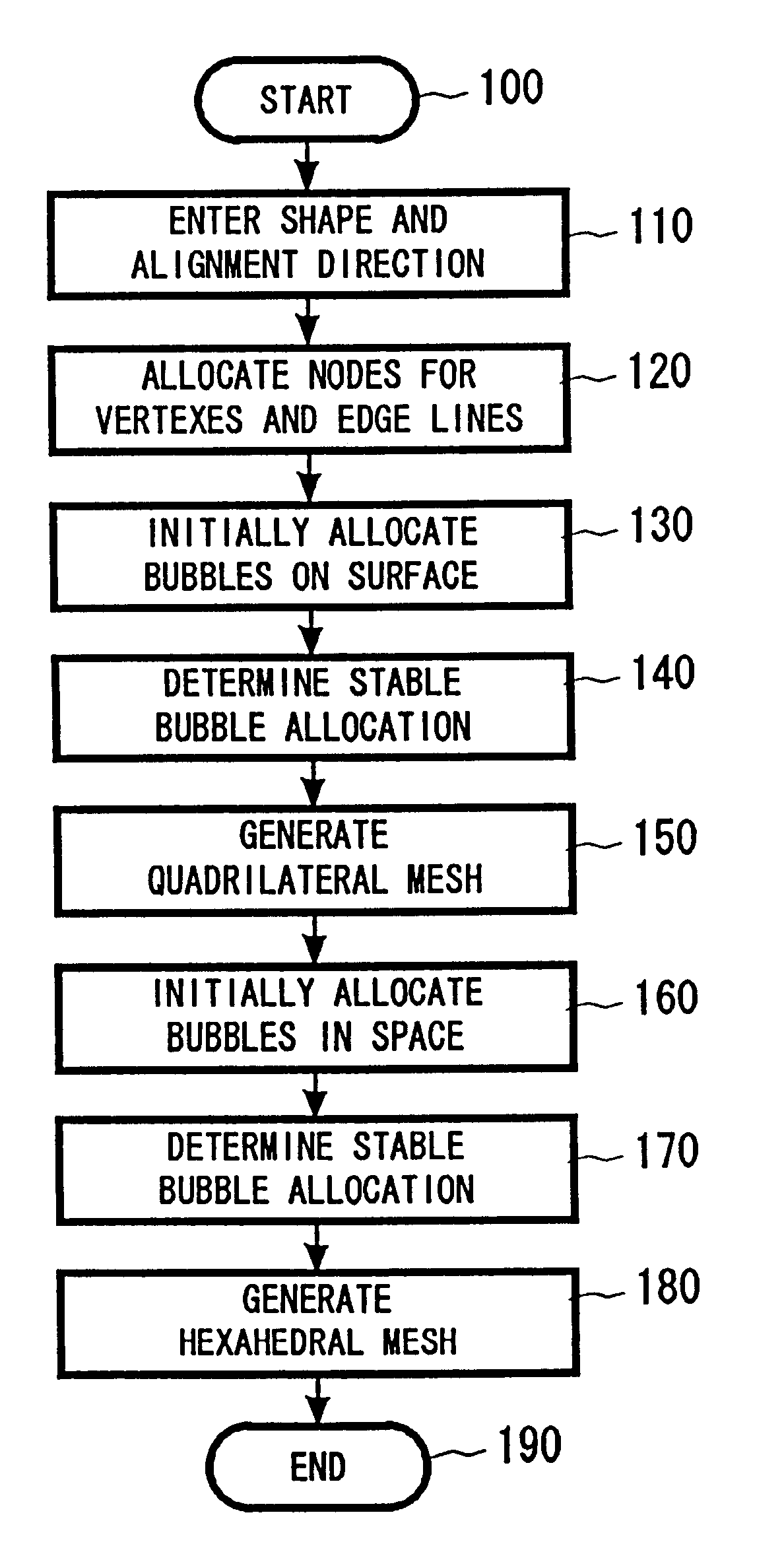
The processing for meshing the object shown in FIG. 1 will now be described referring to the flowchart of FIG. 2.

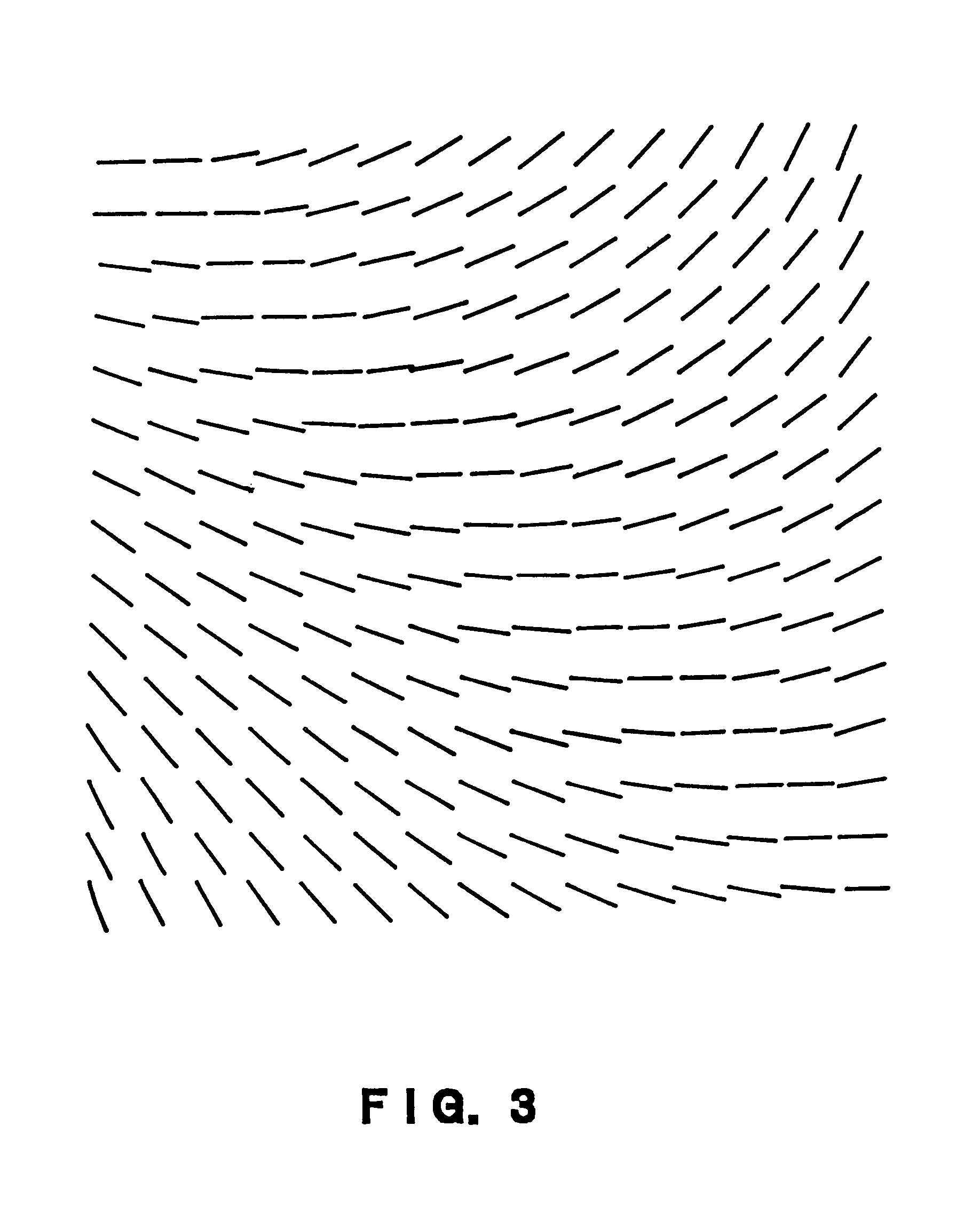
First, an object to be meshed and a mesh alignment direction are entered (step 110). The object to be meshed is that which is shown in FIG. 1. The mesh alignment direction represents the dire...


PUM


Abstract

A method for automatically generating a mesh (e.g., a quadrilateral mesh, a hexahedral mesh, and the like) includes inputting a geometric model to be meshed, generating a plurality of bubbles within a region of the geometric model, determining a stable allocation of the bubbles by moving the bubbles using a force defined by a potential field provided for the bubbles and controlling a number of the bubbles, and generating the mesh by connecting centers of adjacent bubbles.

Description

1. Field of the InventionThe present invention relates to a meshing method, and more particularly to a meshing method using bubbles.2. Description of the Related ArtMeshing or mesh generation is a process for dividing a geometric model-generated computer-aided design (CAD) into a set of small elements. A two-dimensional mesh is provided mainly by a triangular mesh or a quadrilateral mesh. In a computer simulation, such as an analysis of a car crash, a reliable solution cannot be obtained by using a triangular mesh, and a quadrilateral mesh is often employed.However, while a bubble mesh method for the automatic generation of a triangular mesh is established, as described in, for example, Japanese Unexamined Patent Publication No. Hei 7-230487 and No. Hei 8-315183, there are very few practical methods for automatically generating a quadrilateral mesh. Therefore, in generating a quadrilateral mesh, many analysts rely on a method that is labor-intensive and time-consuming (e.g., several...

Claims


Application Information

Patent Timeline
Patent Type & Authority Patents(United States)
IPC IPC(8): G06T17/20G06F17/50
CPCG06T17/20
Inventor ITOH, TAKAYUKIINOUE, KEISUKEYAMADA, ATSUSHIFURUHATA, TOMOTAKE
Owner IBM CORP
Learn More