Communication monitoring apparatus

a technology of communication monitoring and monitoring apparatus, which is applied in the field of communication monitoring apparatuses, can solve the problems of inadequacies of networks, increased complexity of management information tables, and complex selection range of communication protocols of network 10

Inactive Publication Date: 2001-07-10
YOKOGAWA ELECTRIC CORP
View PDF2 Cites 38 Cited by
  • Summary
  • Abstract
  • Description
  • Claims
  • Application Information

AI Technical Summary

Problems solved by technology

Although these communication monitoring apparatuses are appropriate for use on a simple-structured network, they are not appropriate for networks including small scale terminals ard apparatuses or networks which perform communication by selecting different communication methods, as explained below.
Moreover, the selection range of the communication protocols of the network 10 has increased and has correspondingly become complicated.
Then, the management information tables become complicated even for conventional LAN's.
Yet, the commands become further complicated.
And in the end, the scale of the protocol software installation become even more larger.
The installing of the above mentioned analyzing process which the computer 20 is performing according to the conventional method in the small scale terminals and apparatuses such as the portable terminals also increases the burden of the computer 20.
Consequently, because the specified computer aides

Method used


Image

  • Communication monitoring apparatus
  • Communication monitoring apparatus
  • Communication monitoring apparatus

Examples


embodiment 1

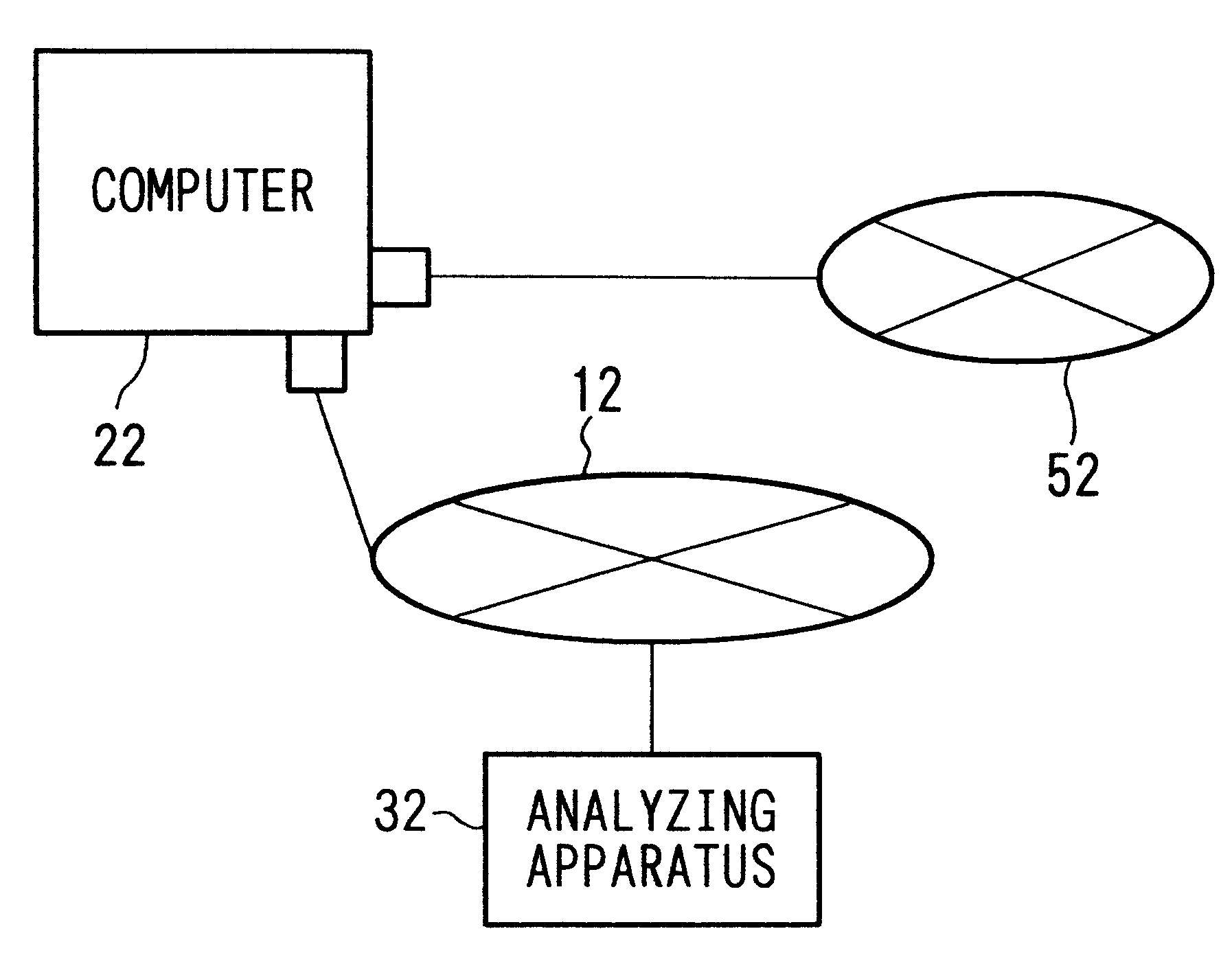
FIG. 1 is a block diagram which illustrates the structure of a simplified version of a communication monitoring apparatus according to the first preferred embodiment of the present invention. In FIG. 1, 12 may be, for example, a network which forms a LAN using cables such as 10BASE-T, and 52 may be, for example, a network which forms a LAN using wireless transmission.

22 is a computer which is connected to both the network 22 and the network 52, and which mounts a communication apparatus for the above mentioned wireless LAN in order to perform communications with other computers connected to the network 52 which may be a wireless LAN and such. This computer 22 is simply the computer 20 in FIG. 4 which now mounts a communication apparatus for the above mentioned wireless LAN. The computer 22 may also be a terminal or a relaying apparatus / connecting apparatus.

In addition, the computer 22 possesses a function for transmitting the bit array sent from the network 52 to the computer 22 by ...

embodiment 2

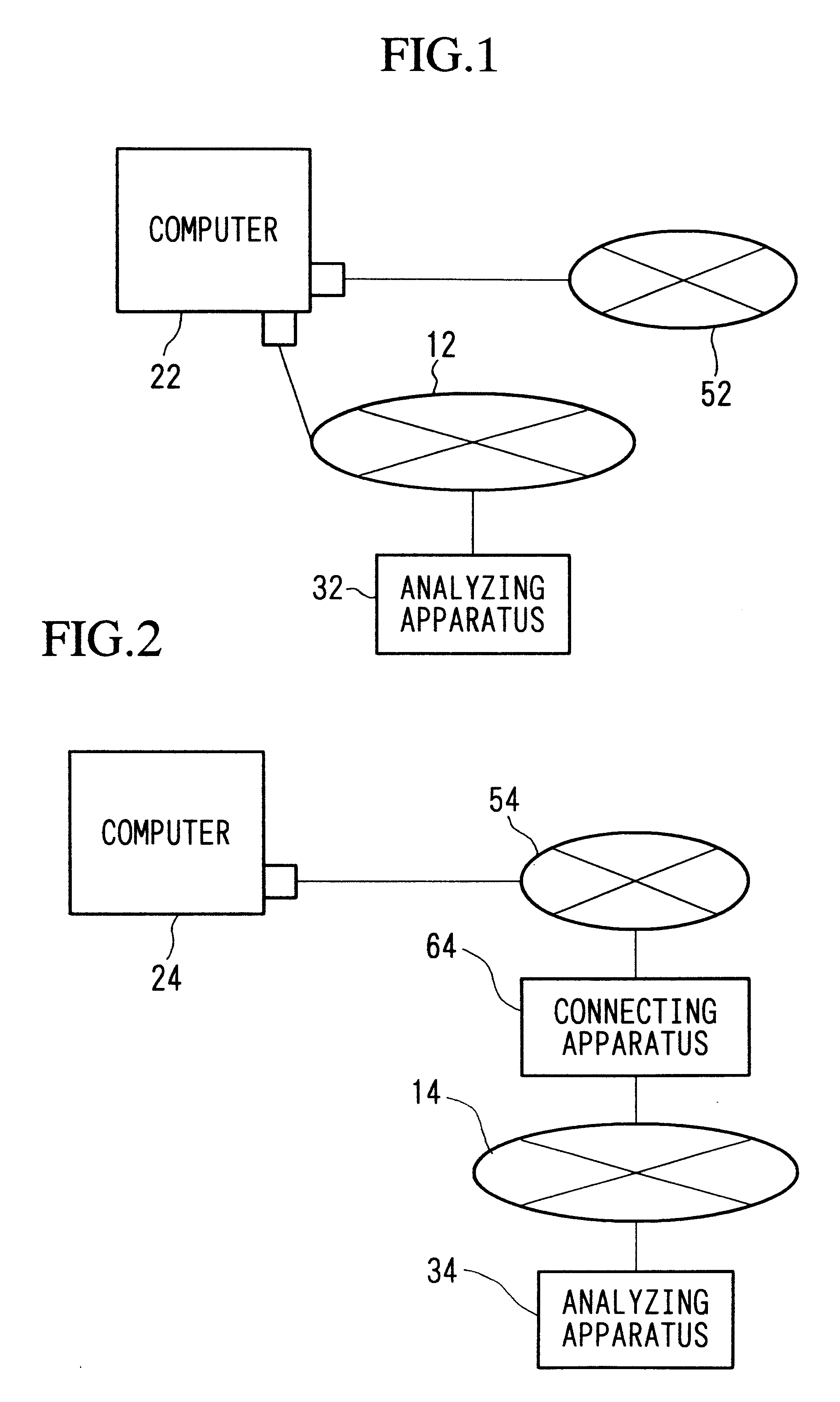
FIG. 2 is a block diagram which illustrates the structure of a simplified version of a communication monitoring apparatus according to the second preferred embodiment of the present invention. According to FIG. 2, 14 may be, for example, a network which forms a LAN using cables such as 10BASE-5, and 54 may be, for example, a network which forms a mobile communication network where mobile terminals are connected to each through wireless transmission.

24 is a computer connected to the network 54, and performs communications with other computers (not shown in diagram) by using the communication protocol used within the network 54. This computer 24 may be, for example, a portable terminal which can be mobile, and performs communications with other computers through wireless transmission. Here, the computer 24 need not be limited to portable terminals, and may be, for example, a base station or such.

34 is an analyzing apparatus connected to the network 14, and is an analyzing apparatus wh...

embodiment 3

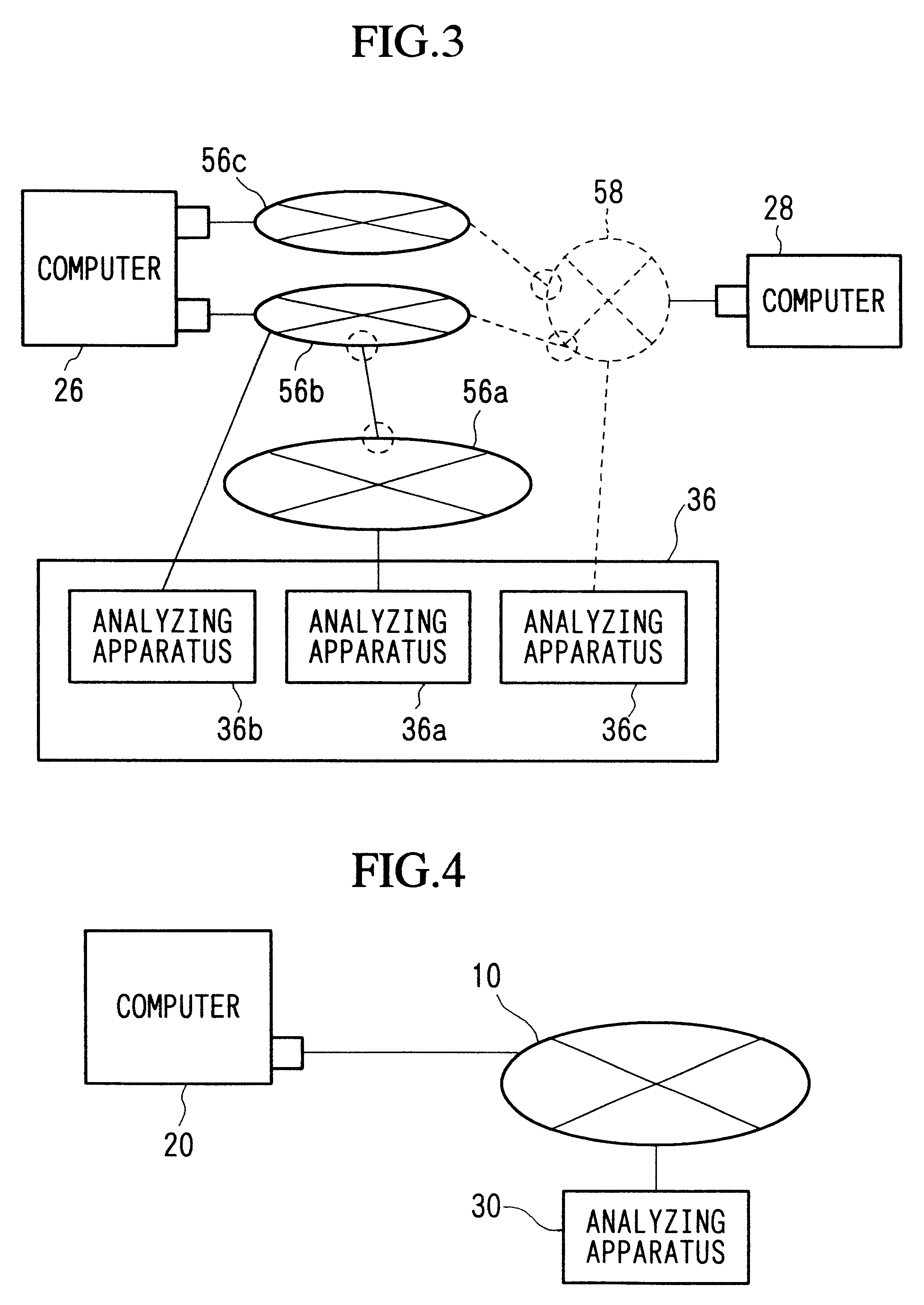
FIG. 3 is a block diagram which illustrates the structure of a simplified version of a communication monitoring apparatus according to the third preferred embodiment of the present invention. In FIG. 3, the computer 26 is a computer which is identical to the computer 22 illustrated in FIG. 1. And the computer 28 is a computer which is identical to the computer 24 illustrated in FIG. 2. As shown in FIG. 3, the computer 26 is connected to the network 56b and the network 56c, while the computer 28 is connected to the network 58. In addition, the network 56b and the network 58 are connected together, and the network 56c and the network 58 are also connected together.

Furthermore, the network 56a is connected to the networks 56b, 56c, 58. The analyzing apparatus 36 which is connected to the network 56a possesses an analyzing apparatus 36a, an analyzing apparatus 36b, and an analyzing apparatus 36c, divides the analyzing process, and mutually communicates the analysis result. The analyzing...


PUM


Abstract

The present invention has the objective of offering an apparatus which comprehensively monitors networks which include small-scale computers and small-scale management protocols which are to be installed. In order to achieve the above objective, with respect to a system formed by a computer 22 and an analyzing apparatus 32 which are connected to a network 12, the present invention has the computer 22 connected to a network 52, and the computer 22 transmits a bit array received via the network 52 to the analyzing apparatus 32 as data. And the analyzing apparatus 32 analyzes the bit array, transmits the analysis result to the computer 22, and aides in the communication of the computer 22.

Description

1. Technical Field of the InventionThe present invention relates to communication monitoring apparatuses. More particularly, it relates to communication monitoring apparatuses which monitors the transfer of data communications performed among computers which are connected over a network.2. Description of the Related ArtBecause communication monitoring apparatuses prevent trouble over networks beforehand and are aware of how the networks are being used, they are used on different types of networks to understand locations which may produce trouble over networks. For example, a communication monitoring apparatus on a local area network (hereinafter, referred to as LAN) commonly use a management standard called SNMP (Simple Network Management Protocol). Relevant facts of standards which are conventionally used for communication monitoring apparatuses will be explained below.FIG. 4 is a diagram which illustrates a simplified structure of a typical communication monitoring apparatus withi...

Claims


Application Information

Patent Timeline
IPC IPC(8): H04L12/26H04L69/40
CPCH04L43/00H04L12/2602
Inventor HONDA, YOSHIZOU
Owner YOKOGAWA ELECTRIC CORP
Why Eureka
Try Eureka