Self-contained hose assembly for a pressurized canister

a self-contained, canister technology, applied in the direction of mechanical equipment, transportation and packaging, liquid transfer devices, etc., can solve the problems of requiring manual assembly, affecting the quality of hose assembly, so as to facilitate automatic packing and shipping of completed pressurized canisters, reduce the risk of hose snagging and tearing, and facilitate the effect of handling

Inactive Publication Date: 2001-07-17
HSIAO CHUNG J
View PDF18 Cites 42 Cited by
  • Summary
  • Abstract
  • Description
  • Claims
  • Application Information

AI Technical Summary

Benefits of technology

It is a further object of the present invention to have a self-contained hose and valve assembly which would facilitate automated packing and shipping of completed pressurized canisters.
It is a further object of the present invention to have pressurized canisters which present reduced hazards of the hose snagging, tearing or the like in storage prior to use of the devices.
The present invention is a hose and valve assembly in which the hose and valve assembly is a self-contained unit suitable for automated installation onto a pressurized canister. The hose and valve assembly is comprised of a valve having an inlet and outlet which are connected by a channel defined by the valve through which the pressurized material contained with canister can flow, and a flexible hose, one end of which is securely and operably attached to the outlet of the valve. Preferably, the hose and valve assembly further comprises a base that supports the valve. In the preferred embodiment, the hose encircles the valve and is positioned within the circumference of the base, such that the hose does not extend beyond the edge of the base. The hose may be constrained in place by a cover that houses the hose and valve and is secured onto the base. Alternatively, the hose may be removably held in place against the base or the exterior of the valve by any suitable adhesive or mechanical fastener, for example a flexible wire. The hose and valve, and optionally the base and cover, are thus assembled into a self-contained hose and valve assembly that can be readily handled by automated machinery.

Problems solved by technology

Certain types of pressurized canisters, however, are unsuitable for hose attachment by the user due to the high pressures involved and the need for a secure attachment between the hose and valve that does not leak.
Further, such tire inflation systems contain materials which are potentially damaging if accidentally released, such as rubberized compounds for effectuating a temporary repair on a tire.
Pre-assembling hoses onto valves at the factory presents some problems, however, in that the assembly process typically must be performed by hand.
Automated installation of the hose and valve assembly onto the pressurized canister is difficult because of the non-symmetric shape of the hose and valve assembly.
Additional difficulties arise when a flexible hose is utilized, in that automated mechanisms cannot readily be modified to reliably place the flexible and / or unpredictably shaped hose and valve assembly onto a pressurized canister.
The non-symmetric and / or flexible hose further causes difficulties in packaging the completed canister assemblies for shipment because it is difficult and costly to re-design automated machines to handle canisters with a rigid protruding hose or a flexible hose strapped to the side.
Even at this stage, flexible hoses attached to the outside of the canister can potentially cause problems because the hose can become entangled in other items in the trunk and become snagged, torn or the like and disabled from use.

Method used


Image

  • Self-contained hose assembly for a pressurized canister
  • Self-contained hose assembly for a pressurized canister
  • Self-contained hose assembly for a pressurized canister

Examples


Embodiment Construction

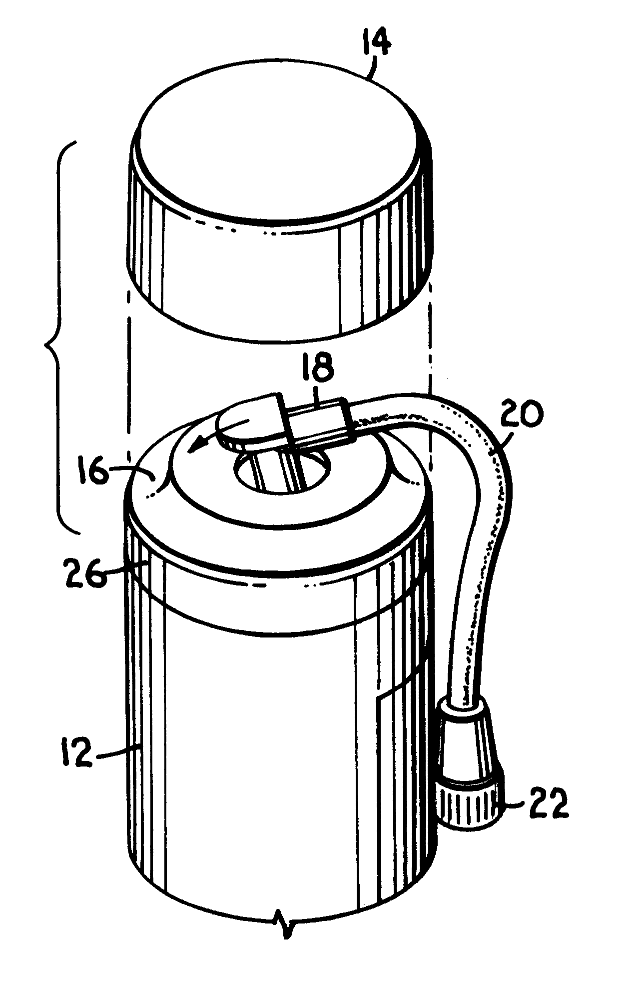
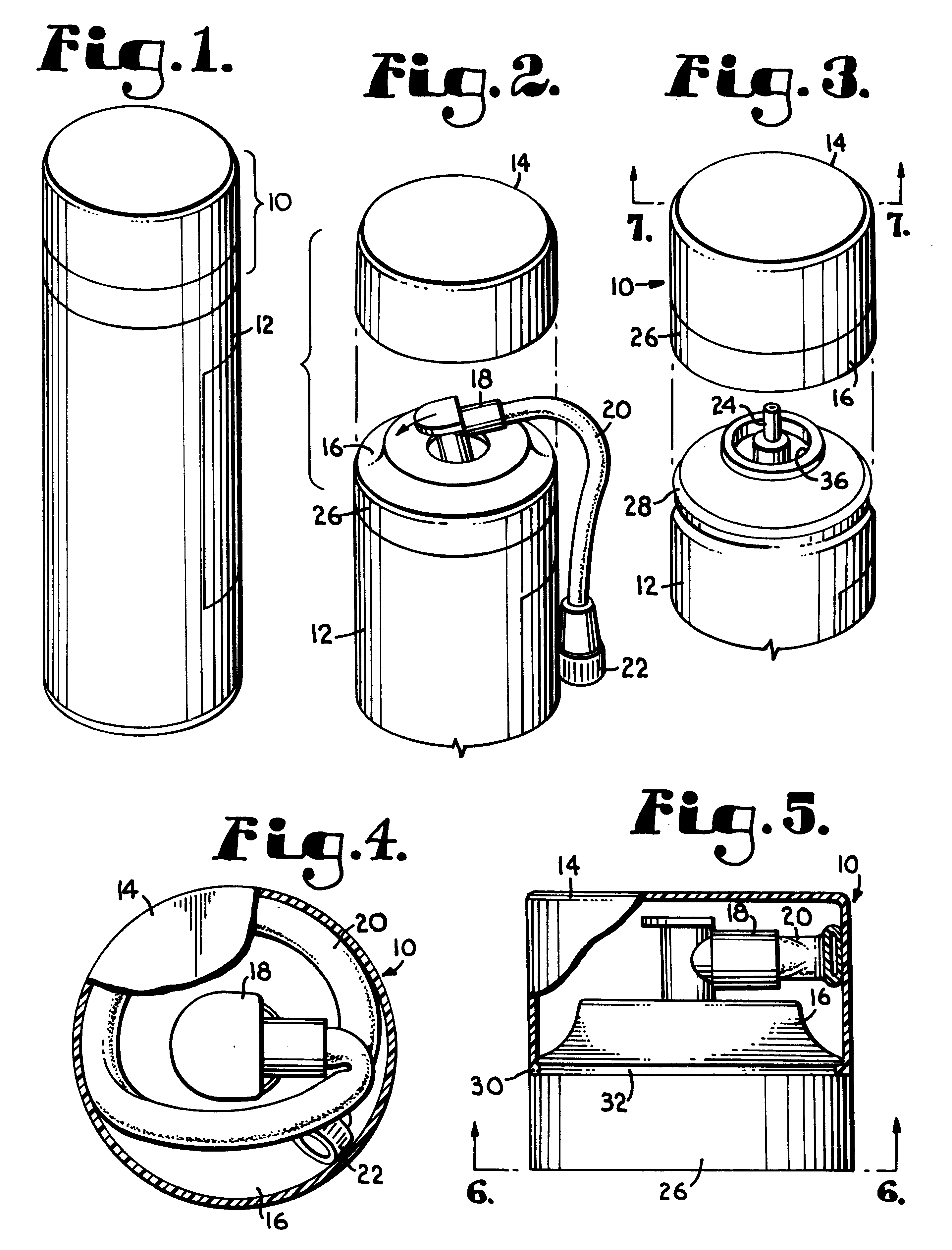
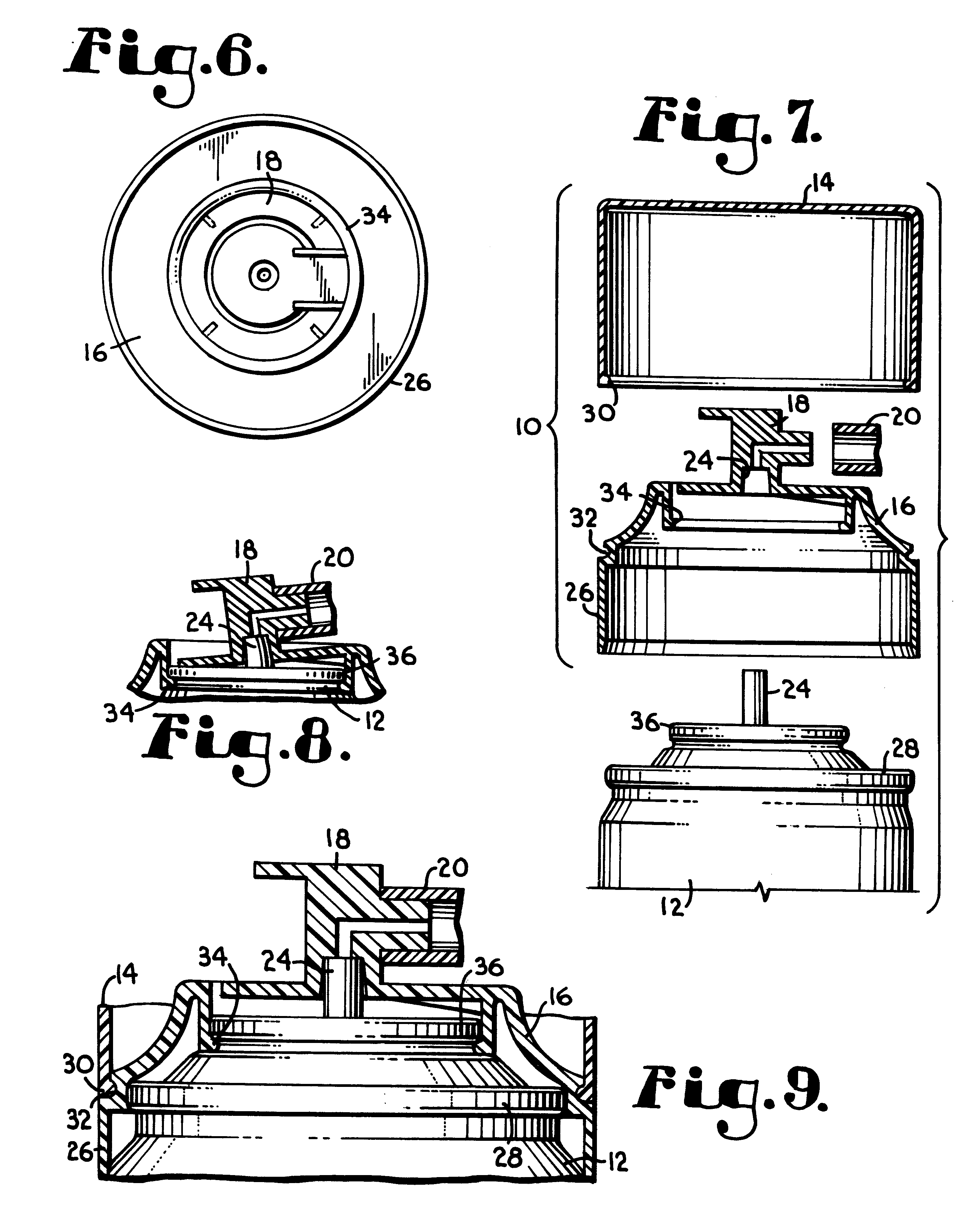
Referring first to FIG. 1, the present invention device is a self-contained hose and valve assembly, generally designated by the numeral 10, for use with a canister 12 containing pressurized materials, such as tire inflation material. FIG. 1 depicts one embodiment of hose and valve assembly 10 as it would appear assembled and installed on a canister 12 and ready for purchase and storage by a consumer.

FIG. 2 depicts a cover 14 separated from a base 16 of hose and valve assembly 10 to expose valve 18 and attached hose 20, all of which are part of the hose and valve assembly 10. As used herein, valve 18 refers to an external valve mechanism having an inlet and outlet connected by a channel defined by the valve through which the pressurized material contained in the canister can flow when valve 18 is depressed. In use, a consumer removes cover 14, as shown in FIG. 2, thereby freeing hose 20 for use. The consumer then directs hose nozzle 22 at the desired point of application and depress...


PUM


Abstract

The invention is directed to a self-contained hose and valve assembly for installation on a pressurized canister. In one embodiment of the invention, a flexible hose is wrapped around a valve and is removably attached to a base supporting the valve. The hose and valve are housed within a cover that is removably secured to the base to form a self-contained unit. In an additional embodiment of the invention, the self-contained hose and valve assembly does not contain a cover and the hose is instead attached to the valve or the base by an adhesive or a mechanical fastener, such as a shrink sleeve to form the self-contained unit. The self-contained hose and valve assembly of the present invention reduces difficulties relating to installation, packaging, and storage of hose and valve assemblies for use with pressurized containers, such as tire inflation systems, in that the hose is securely affixed within the assembly and therefore will not interfere with automated assembly, installation, or packaging devices and will not become entangled with items in the trunk of a car during storage by the user.

Description

BACKGROUND OF INVENTIONThis invention generally relates to a hose assembly for use with canisters containing pressurized material such as tire inflation material, and the like, and a method of assembling the same. More specifically, the invention relates to a self-contained combined hose and valve assembly that can be installed on a pressurized canister by an automated means, such as by a capping machine.Various pressurized canisters marketed today utilize hose and / or nozzle mechanisms for conveying and directing the material contained in the canister to the specific location at which the material is to be used. Typically these hose and / or nozzle mechanisms are received by the consumer as a separate piece attached to the outside of the canister, and in order to utilize the hose or nozzle, the user is required to attach the hose or nozzle onto a valve on the canister that communicates with the interior of the canister. Certain types of pressurized canisters, however, are unsuitable f...

Claims


Application Information

Patent Timeline
Patent Type & Authority Patents(United States)
IPC IPC(8): B65D83/14B65D83/16
CPCB65D83/205B65D83/756B65D83/303Y10T137/6962
Inventor HSIAO, CHUNG J.
Owner HSIAO CHUNG J
Why Eureka
Try Eureka