
Traction stud mount and method of manufacturing and mounting

a technology of stud mounting and mounting bracket, which is applied in the direction of endless track vehicles, vehicles, transportation and packaging, etc., can solve the problems of time-consuming assembly and disassembly of the various stud mounting components, improving traction, and relatively complicated and expensive multiple pieces

Inactive Publication Date: 2001-07-24
INT ENG & MFG
View PDF17 Cites 30 Cited by
  • Summary
  • Abstract
  • Description
  • Claims
  • Application Information

AI Technical Summary

Benefits of technology

It is a further object of the present invention to provide a new and novel stud mount which will allow snowmobile racers to quickly change the snowmobile traction studs, mounted on an endless snowmobile drive track, without the necessity of replacing and / or accounting for a plurality of stud fastener parts threadedly coupled to a stud.
A snowmobile typically includes wear rods which are disposed along the inner bottom run of the drive track and bear against or ride along track clips that are mounted on the drive track adjacent to windows passing between the inner and outer surfaces of the track. With continual operation, substantial heat is generated due to friction and the track can be heated substantially. In the area of the track guides, the heat sometimes becomes intense and if the heat becomes too high, there is concern that the track embedded fiberglass resin reinforcing rods may deteriorate. It has been found, according to the present invention, that coupling the stud mounts directly to reinforcing rods improve the transmission of heat away from the rod. Accordingly, it is an object of the present invention to provide a new and novel stud mount which will function to dissipate heat generated in the drive track.

Problems solved by technology

Early attempts at improving traction on ice included a relatively complicated and expensive multiple piece grouser assembly such as that illustrated in U.S. Pat. No. 2,040,696 issued to E. A. Johnston on May 12, 1936.
The turnaround time required to replace broken studs is particularly important to snowmobile racers and the assembly and disassembly of the various stud mounting components are time consuming.
The cutting of such holes is time consuming and the user may not optimally place the holes to maximize traction.
Studs which are deflected relative to the track, tend to deflect or tip into a negative attitude.
In the area of the track guides, the heat sometimes becomes intense and if the heat becomes too high, there is concern that the track embedded fiberglass resin reinforcing rods may deteriorate.

Method used


Image

  • Traction stud mount and method of manufacturing and mounting
  • Traction stud mount and method of manufacturing and mounting
  • Traction stud mount and method of manufacturing and mounting

Examples


Embodiment Construction

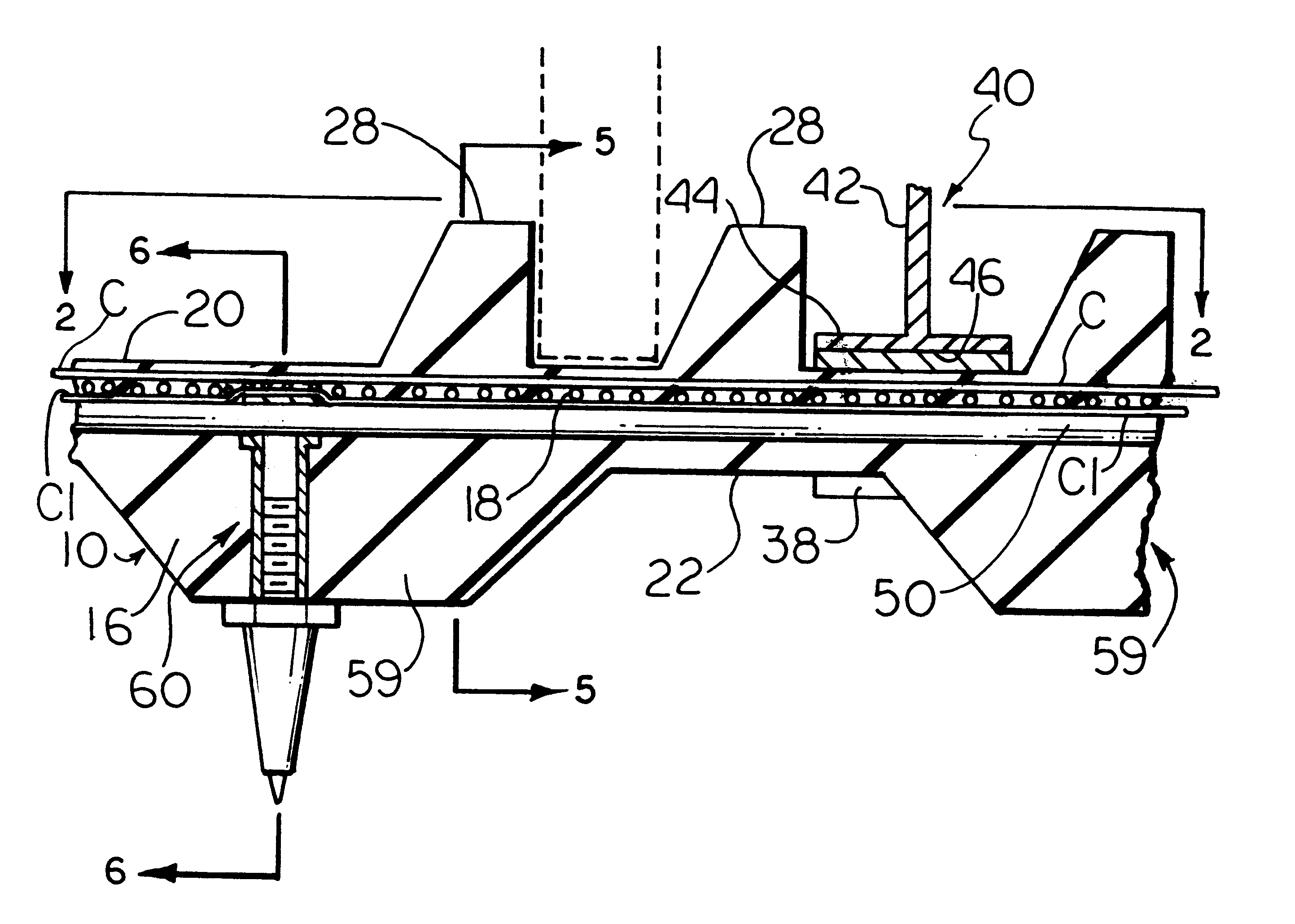
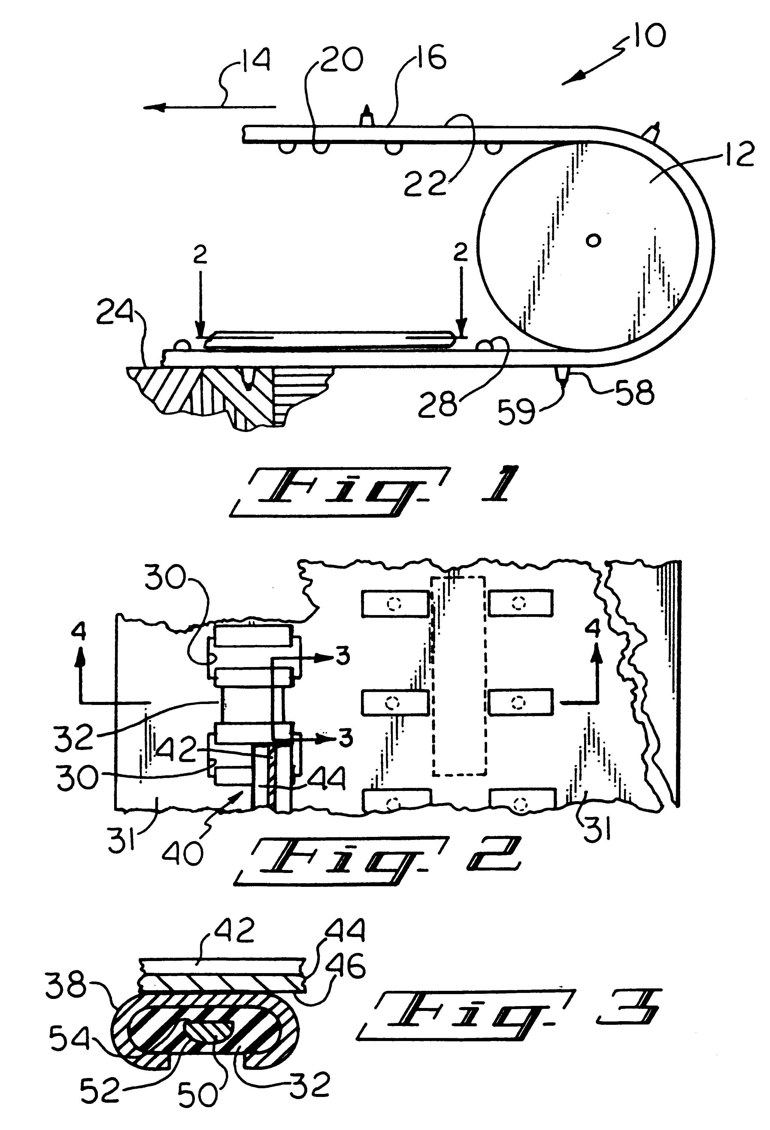
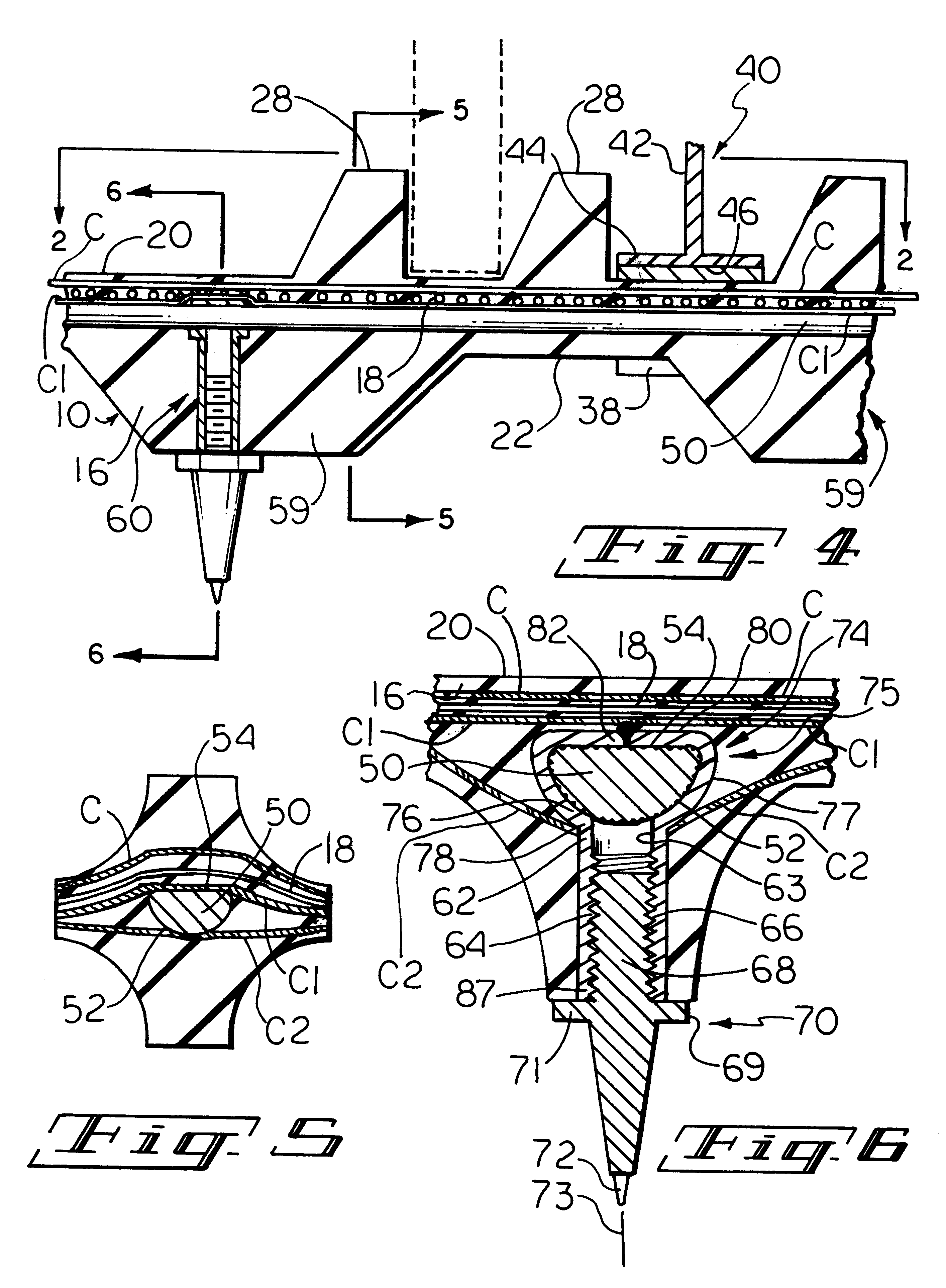
A snowmobile drive track constructed according to the present invention, generally designated 10, includes an endless drive belt 16 trained around a pair of drive sprockets or wheels, one of which is illustrated at 12, for driving the belt 16 in endless path represented by the arrow 14. The endless belt 16 may suitably comprise flexible rubber having a plurality of longitudinally extending polyester cords 18 (FIG. 4) which are sandwiched between a pair of cloth webs C and C 1 embedded therein to strengthen the track.

The belt 16 includes an inner face 20 and an outer face 22 which, as it passes along the lower run of the belt, engages a surface 24 to be traversed. The inner track surface 20 integrally mounts spaced apart pairs of laterally spaced drive lugs 28 which are spaced along the length of the inside of the belt 16 for engaging the drive wheels 12 as usual. The belt 16 includes a plurality of laterally spaced apart endless parallel sub-belts 31 of differing widths coupled toge...


PUM


Abstract

A one-piece stud mount for mounting a traction stud on a reinforcing rod adapted to be embedded in a yieldable drive track. The stud mount includes an elongated, stud receiving receptacle having a threaded opening therein for threadedly receiving a traction stud and a transversely disposed head defining an aperture which has a shape complemental to the shape of the rod for slidably receiving the rod prior to the molding of the track. The invention contemplates a method of manufacturing the stud mount and mounting the stud mount on a track reinforcing bar. The invention also contemplates a method of manufacturing a track in which the stud mount is embedded after being mounted on a reinforcing rod which is also embedded in the track.

Description

1. Field of the InventionThis invention relates to a stud mount for mounting a traction stud on a vehicle drive member and more particularly to a one-piece stud mount and method of making a one-piece stud mount which is slidably received on a reinforcing rod that is thereafter embedded in an endless yieldable snowmobile drive track.2. Description of the Prior Art and ObjectsA snowmobile is a motor driven machine which is propelled by an endless drive track typically formed of resilient material such as rubber. Early attempts at improving traction on ice included a relatively complicated and expensive multiple piece grouser assembly such as that illustrated in U.S. Pat. No. 2,040,696 issued to E. A. Johnston on May 12, 1936. More recent attempts at improving the traction capability of the snowmobile while traversing slippery surfaces include traction improving products, such as the ice stud illustrated in U.S. Pat. No. 3,973,808 issued on August 10 to Jansen et al. U.S. Pat. No. 3,83...

Claims


Application Information

Patent Timeline
IPC IPC(8): B62D55/28B62D55/18B62D55/27B62D55/253
CPCB62D55/28
Inventor MUSSELMAN, JAMESMUSSELMAN, ROBERTMUSSELMAN, MARK
Owner INT ENG & MFG
Learn More